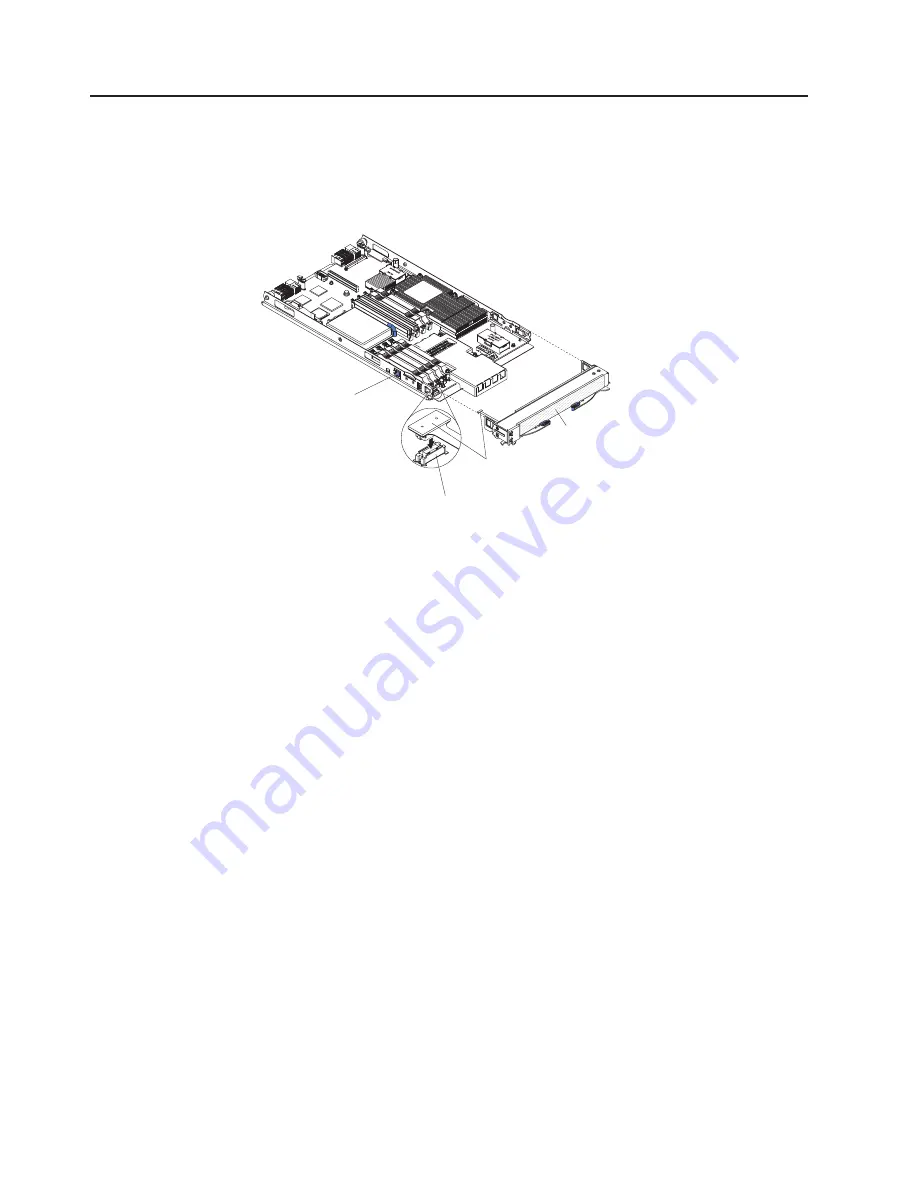
Removing
the
bezel
assembly
To
install
certain
options,
you
must
first
remove
the
bezel
assembly.
The
following
illustration
shows
how
to
remove
the
blade
server
bezel
assembly.
The
illustration
and
instructions
also
apply
to
the
MPE
bezel
assembly,
except
that
the
MPE
does
not
have
a
control-panel
connector.
Bezel-assembly
release (both sides)
Bezel assembly
Control-panel
connector
Control-panel
cable
To
remove
the
blade
server
bezel
assembly,
complete
the
following
steps:
1.
Read
the
safety
information
beginning
on
page
v
and
“Installation
guidelines”
on
page
17.
2.
Open
the
blade
server
cover
(see
“Opening
the
blade
server
cover”
on
page
20
for
instructions).
3.
If
you
are
removing
the
bezel
assembly
from
the
blade
server
and
an
expansion
unit
is
connected
to
the
blade
server,
remove
the
expansion
unit
(see
“Removing
an
expansion
unit”
on
page
21).
4.
Press
the
bezel-assembly
release
and
pull
the
bezel
assembly
away
from
the
blade
server
approximately
1.2
cm
(0.5
inch).
5.
If
you
are
removing
the
bezel
assembly
from
the
blade
server,
disconnect
the
control-panel
cable
from
the
control-panel
connector.
6.
Pull
the
bezel
assembly
away
from
the
blade
server.
7.
Store
the
bezel
assembly
in
a
safe
place.
22
BladeCenter
LS21
Type
7971
and
LS41
Type
7972:
Installation
and
User’s
Guide
Summary of Contents for LS21 - BladeCenter - 7971
Page 3: ...BladeCenter LS21 Type 7971 and LS41 Type 7972 Installation and User s Guide...
Page 24: ...12 BladeCenter LS21 Type 7971 and LS41 Type 7972 Installation and User s Guide...
Page 78: ...66 BladeCenter LS21 Type 7971 and LS41 Type 7972 Installation and User s Guide...
Page 82: ...70 BladeCenter LS21 Type 7971 and LS41 Type 7972 Installation and User s Guide...
Page 83: ......
Page 84: ...Part Number 42C4897 Printed in USA 1P P N 42C4897...


