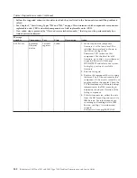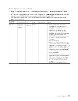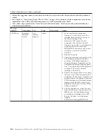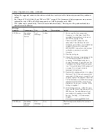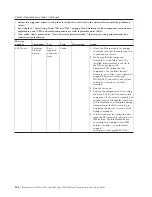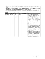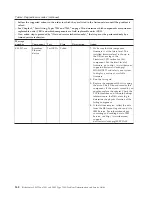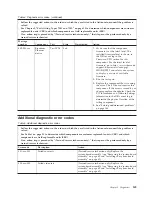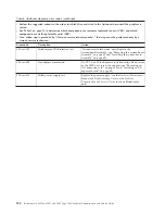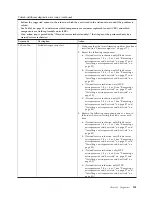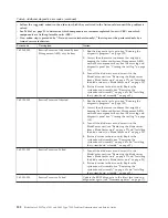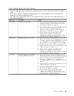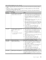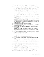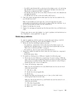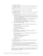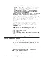
Table 5. Additional diagnostic error codes (continued)
v
Follow the suggested actions in the order in which they are listed in the Action column until the problem is
solved.
v
See Table 1 on page 21 to determine which components are customer replaceable units (CRU) and which
components are field replaceable units (FRU).
v
If an action step is preceded by “(Trained service technician only),” that step must be performed only by a
trained service technician.
Error code
Description
Action
180-xxx-003
Failed system board LED test.
(Trained service technician only) Replace the
system-board assembly (see “Removing the system-board
assembly” on page 62 and “Installing the system-board
assembly” on page 62).
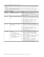
201-198-xxx
Memory test aborted. See Diagnostics
logs.
1.
Restart the server (see “Turning off the blade server”
on page 6 and “Turning on the blade server” on page
5).
2.
Run the diagnostic test again (see “Running the
diagnostic programs” on page 109).
3.
Reinstall the diagnostic program (see “Firmware
updates” on page 17).
4.
See the error log for additional information.
201-199-xxx
Unexpected error. Test aborted. See
Diagnostics logs.
1.
Restart the server (see “Turning off the blade server”
on page 6 and “Turning on the blade server” on page
5).
2.
Run the diagnostic test again (see “Running the
diagnostic programs” on page 109).
3.
Reinstall the diagnostic program (see “Firmware
updates” on page 17).
4.
See the error log for additional information.
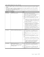
201-xxx-PBD
Test failed.
v
P = CPU Number (1 - 4)
v
B = Failing bank/pair number
v
D = Failing DIMM number within
failing CPU # P
v
D = 9: Both DIMMs in the failing
bank/pair of DIMMs
1.
Reseat the failing DIMMs; then, run the memory
diagnostic test again (see “Removing a memory
module” on page 37 and “Installing a memory
module” on page 38).
2.
Replace the failing DIMMs (see “Removing a memory
module” on page 37 and “Installing a memory
module” on page 38); then, run the memory
diagnostic test again.
3.
(Trained service technician only) Replace the
system-board assembly (see “Removing the
system-board assembly” on page 62 and “Installing
the system-board assembly” on page 62).
156
BladeCenter LS22 Type 7901 and LS42 Type 7902: Problem Determination and Service Guide
Summary of Contents for LS42 - BladeCenter - 7902
Page 1: ...BladeCenter LS22 Type 7901 and LS42 Type 7902 Problem Determination and Service Guide...
Page 2: ......
Page 3: ...BladeCenter LS22 Type 7901 and LS42 Type 7902 Problem Determination and Service Guide...
Page 12: ...x BladeCenter LS22 Type 7901 and LS42 Type 7902 Problem Determination and Service Guide...
Page 76: ...64 BladeCenter LS22 Type 7901 and LS42 Type 7902 Problem Determination and Service Guide...
Page 192: ...180 BladeCenter LS22 Type 7901 and LS42 Type 7902 Problem Determination and Service Guide...
Page 193: ......
Page 194: ...Part Number 49Y0107 Printed in USA 1P P N 49Y0107...

