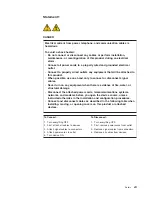
background image

Statement


1


DANGER

Electrical


current


from


power,


telephone,


and


communication


cables


is


hazardous.


To


avoid


a


shock


hazard:


v


Do


not


connect


or


disconnect


any


cables


or


perform


installation,


maintenance,


or


reconfiguration


of


this


product


during


an


electrical


storm.


v


Connect


all


power


cords


to


a


properly


wired


and


grounded


electrical


outlet.


v


Connect


to


properly


wired


outlets


any


equipment


that


will


be


attached


to


this


product.


v


When


possible,


use


one


hand


only


to


connect


or


disconnect


signal


cables.


v


Never


turn


on


any


equipment


when


there


is


evidence


of


fire,


water,


or


structural


damage.


v


Disconnect


the


attached


power


cords,


telecommunications


systems,


networks,


and


modems


before


you


open


the


device


covers,


unless


instructed


otherwise


in


the


installation


and


configuration


procedures.


v


Connect


and


disconnect


cables


as


described


in


the


following


table


when


installing,


moving,


or


opening


covers


on


this


product


or


attached


devices.


To


Connect:


To


Disconnect:


1.


Turn


everything


OFF.


2.


First,


attach


all


cables


to


devices.


3.


Attach


signal


cables


to


connectors.


4.


Attach


power


cords


to


outlet.


5.


Turn


device


ON.


1.


Turn


everything


OFF.


2.


First,


remove


power


cords


from


outlet.


3.


Remove


signal


cables


from


connectors.


4.


Remove


all


cables


from


devices.


Safety


vii

Summary of Contents for LS42 - BladeCenter - 7902

Page 1: ......

Page 2: ......

Page 3: ...BladeCenter LS22 and LS42 Type 7901 and 7902 Installation and User s Guide...

Page 4: ...and the Warranty and Support Information document for your blade server type on the IBM Documentation CD Second Edition August 2008 Copyright International Business Machines Corporation 2008 US Gover...

Page 5: ...assembly 22 Installing a SAS drive tray 23 Removing a SAS drive tray 24 Installing a SAS drive 25 Removing a SAS drive 26 Installing additional memory 27 Installing an additional microprocessor 29 Ins...

Page 6: ...nostic tools overview 63 ServerGuide problems 64 Appendix Getting help and technical assistance 65 Before you call 65 Using the documentation 65 Getting help and information from the World Wide Web 66...

Page 7: ...rt eerst de veiligheidsvoorschriften Ennen kuin asennat t m n tuotteen lue turvaohjeet kohdasta Safety Information Avant d installer ce produit lisez les consignes de s curit Vor der Installation dies...

Page 8: ...r statement with translated versions of the caution or danger statement in the Safety Information document For example if a caution statement is labeled Statement 1 translations for that caution state...

Page 9: ...quipment when there is evidence of fire water or structural damage v Disconnect the attached power cords telecommunications systems networks and modems before you open the device covers unless instruc...

Page 10: ...de if not properly used handled or disposed of Do not v Throw or immerse into water v Heat to more than 100 C 212 F v Repair or disassemble Dispose of the battery as required by local ordinances or re...

Page 11: ...nsion card on page 42 If the expansion card bracket does not have to be installed save it in a safe place The blade server comes with a limited warranty For information about the terms of the warranty...

Page 12: ...r and on a label on the side of the blade server that is visible when the blade server is not in the BladeCenter unit The LS22 Type 7901 single width blade server requires only one blade bay in the Bl...

Page 13: ...nd how to configure the blade server The following documentation also comes with the blade server v Problem Determination and Service Guide This document is in Portable Document Format PDF on the IBM...

Page 14: ...d software requirements The IBM Documentation CD contains documentation for your blade server in Portable Document Format PDF and includes the IBM Documentation Browser to help you find information qu...

Page 15: ...rs are listed in order of the most occurrences Click a document to view it and press Crtl F to use the Acrobat search function or press Alt F to use the xpdf search function within the document Click...

Page 16: ...telligent Platform Management Interface IPMI firmware 1 5 compliant v ATI RN 50 video controller v LSI 1064E Serial Attached SCSI SAS controller v Light path diagnostics v Dynamic System Analysis DSA...

Page 17: ...hardware devices and provides the correct configuration programs and device drivers For more information about the ServerGuide Setup and Installation CD see Using the ServerGuide Setup and Installatio...

Page 18: ...itor the power environment by using the management module For more information about configuring and using power throttling see the management module documentation or go to http www ibm com bladecente...

Page 19: ...Ware For a complete list of operating systems that support IBM Director see the IBM Director Compatibility document This document is in Portable Document Format PDF at http www ibm com systems managem...

Page 20: ...ve the blade server from the BladeCenter unit and remove the cover to see the components For the LS42 Type 7902 blade server you must remove the MPE unit to see the components on the blade server syst...

Page 21: ...select button Press this button to associate the shared BladeCenter unit keyboard video and mouse port KVM with the blade server The LED on this button flashes while the request is being processed and...

Page 22: ...ement module Web interface to determine whether local control has been disabled on the blade server Note The operating system in the blade server must provide USB support for the blade server to recog...

Page 23: ...ough the management module to do so v You can turn on the blade server remotely by using the management module v If the blade server is connected to power the power on LED is flashing slowly and the W...

Page 24: ...r For additional information see the IBM BladeCenter Management Module User s Guide Blade server connectors The following illustration shows the system board components including connectors for user i...

Page 25: ...The following illustration shows the MPE components including connectors for user installable optional devices Chapter 2 Power controls and indicators 15...

Page 26: ...16 BladeCenter LS22 and LS42 Type 7901 and 7902 Installation and User s Guide...

Page 27: ...2 and click Go Download and install the latest firmware for the management module installed in your BladeCenter unit see the documentation for your management module v Observe good housekeeping in the...

Page 28: ...ou are ready to install them To reduce the possibility of damage from electrostatic discharge observe the following precautions v Limit your movement Movement can cause static electricity to build up...

Page 29: ...lade server into a different bay you might have to reconfigure the blade server To remove the blade server complete the following steps 1 Read the safety information beginning on page Safety on page v...

Page 30: ...on page 17 2 If the blade server is installed in a BladeCenter unit remove it see Removing the blade server from the BladeCenter unit on page 19 for instructions 3 Carefully lay the blade server down...

Page 31: ...the blade server cover see Opening the blade server cover on page 20 for instructions 3 If the expansion unit has an extraction device such as a thumbscrew or a lever use it to disengage the expansion...

Page 32: ...over on page 20 for instructions 3 If you are removing the bezel assembly from the blade server and an MPE unit or an expansion unit is connected to the blade server remove the expansion unit see Remo...

Page 33: ...m the BladeCenter unit on page 19 for instructions 3 Carefully lay the blade server on a flat static protective surface 4 Open the blade server cover see Opening the blade server cover on page 20 for...

Page 34: ...nes on page 17 2 Carefully lay the blade server on a flat static protective surface 3 Open the blade server cover see Opening the blade server cover on page 20 for instructions 4 If an MPE unit or an...

Page 35: ...ng the blade server from the BladeCenter unit on page 19 for instructions 3 Carefully lay the blade server on a flat static protective surface 4 Open the blade server cover see Opening the blade serve...

Page 36: ...expansion unit is connected to the blade server remove the device see Removing an expansion unit on page 21 4 Press the release lever away from the SAS drive then remove the SAS drive Note Press the r...

Page 37: ...le for the blade server are 1 GB 2 GB and 4 GB v All DIMMs must be installed in pairs of the same size speed type technology and physical design You can use compatible DIMMs from different manufacture...

Page 38: ...open or close them v Grasp the DIMM gently when you remove it from the connector to avoid ejecting it To install a DIMM complete the following steps 1 Read the safety information that begins on page S...

Page 39: ...e connector using the retaining clip slots as guides to align the DIMM with the connector g Simultaneously press down firmly and evenly on both ends of the DIMM until it is completely seated in the co...

Page 40: ...el of BIOS code see Firmware updates on page 59 v The microprocessors terminate themselves therefore no terminator card is required if microprocessor socket 2 is empty on the blade server or on the MP...

Page 41: ...he system board v Hold the edges of the microprocessor Do not touch the contacts on the microprocessor or the contacts on the microprocessor socket Touching these contacts might result in permanent da...

Page 42: ...ink becomes contaminated contact your service technician a Remove the plastic protective cover from the bottom of the heat sink b Make sure that the thermal material is still on the bottom of the heat...

Page 43: ...lat static protective surface 4 Open the blade server cover see Opening the blade server cover on page 20 for instructions 5 If you are installing a standard form factor expansion card in the blade se...

Page 44: ...Center unit on page 19 for instructions 3 Carefully lay the blade server on a flat static protective surface 4 Open the blade server cover see Opening the blade server cover on page 20 for instruction...

Page 45: ...c protective surface 4 Open the blade server cover see Opening the blade server cover on page 20 for instructions 5 If you are removing a standard form factor expansion card from the blade server and...

Page 46: ...connector then slide the slots at the back end of the card out of the expansion card standoffs and lift the card out of the blade server 7 If you have other options to install or remove do so now othe...

Page 47: ...ade server to remove it from the card retainer brackets 6 Remove the CFFv card The following illustration shows how to remove a CFFv expansion card from the blade server removing a combination form fa...

Page 48: ...expansion unit is attached to the blade server remove the device see Removing an expansion unit on page 21 6 If a standard form factor expansion card is installed remove it see Removing a standard fo...

Page 49: ...factor combination form factor or high speed expansion card If the blade server has an MPE installed a high speed expansion card can be installed only in the MPE unit See http www ibm com servers ese...

Page 50: ...sion unit I O expansion connector expansion unit I O expansion connector blade server cKVM blade server SAS drive 0 blade server SAS drive 1 blade server HSDC standard form factor expansion card X X H...

Page 51: ...ansion card in the blade server and an expansion unit is installed remove the expansion unit see Removing an expansion unit on page 21 6 Touch the static protective package that contains the expansion...

Page 52: ...6 c If a drive tray is installed in front of SAS connector 1 remove the drive tray see Removing a SAS drive tray on page 24 Save the screws and the drive tray in a safe place d Install the expansion c...

Page 53: ...n be installed in an MPE unit that is attached to the blade server You cannot install a high speed expansion card in a blade server to which an expansion unit will be connected If you are installing a...

Page 54: ...tic protective surface 4 Open the cover see Opening the blade server cover on page 20 for instructions 5 Install the CFFv card The following illustration shows how to install a CFFv expansion card int...

Page 55: ...rface 4 Open the cover see Opening the blade server cover on page 20 for instructions 5 If you are installing the cKVM card in the blade server and an expansion unit is installed remove the expansion...

Page 56: ...unit from a double width type of blade server reinstall the expansion unit see Installing an expansion unit on page 48 3 Close the blade server cover see Closing the blade server cover on page 49 If...

Page 57: ...gins on page Safety on page v and Installation guidelines on page 17 2 If you are installing the bezel assembly on a blade server connect the control panel cable to the control panel connector on the...

Page 58: ...y pulling the cover off the connector see Blade server connectors on page 14 5 If you are installing a new expansion unit touch the static protective package that contains the expansion unit to any un...

Page 59: ...ver cover complete the following steps 1 Read the safety information that begins on page Safety on page v and Installation guidelines on page 17 2 If you removed the bezel assembly install it see Inst...

Page 60: ...de server 3 Select the bay for the blade server An additional bay is required for each blade expansion device that is connected to the blade server Note v When any blade server or device is in blade b...

Page 61: ...Center T unit only For detailed instructions for reinstalling the bezel assembly see the Installation and User s Guide that comes with the BladeCenter T unit If this is the initial installation for th...

Page 62: ...nd the keyboard video mouse select button See Blade server control panel and LEDs on page 11 for information about these buttons and their functions The Ethernet controller on the blade server communi...

Page 63: ...of the BIOS code in the blade server Use it to select the boot protocol and other boot options and to select a power management option For information about using this utility program see Using the PX...

Page 64: ...s choice to view the machine type and model of the blade server the serial number and the revision level or issue date of the BIOS and diagnostics code that are stored in electrically erasable program...

Page 65: ...ord when the blade server starts v Advanced Setup Select this choice to change settings for advanced hardware features Important The blade server might malfunction if these settings are incorrectly co...

Page 66: ...assword override switch see the Problem Determination and Service Guide on the Documentation CD for instructions Using the ServerGuide Setup and Installation CD The ServerGuide Setup and Installation...

Page 67: ...s updated device drivers for most adapters and devices v Provides diskette free installation for supported Windows operating systems v Includes an online readme file with links to tips for the hardwar...

Page 68: ...rol to complete the installation The BladeCenter CD drive must be associated with the blade server before you perform this step Installing the operating system without ServerGuide If you have already...

Page 69: ...the Ethernet controller For device drivers and information about configuring the Ethernet controller see the Broadcom NetXtreme Gigabit Ethernet Software CD that comes with the blade server To find up...

Page 70: ...ility program to perform the following tasks v Set the SAS device scan order v Set the SAS ID for the controller v Manage the SAS RAID configuration To start the LSI Logic Configuration Utility progra...

Page 71: ...systems such as Red Hat Linux 7 3 enable you to select the type of mouse that is being used If you are offered this choice select USB instead of PS 2 Although the mouse might be a PS 2 style device co...

Page 72: ...t you plan to install see http www ibm com systems management Downloading operating system installation instructions You can download operating system installation instructions from the IBM Web site T...

Page 73: ...ols are available to help you diagnose and solve hardware related problems v POST beep codes The power on self test beep codes can indicate the detection of a problem One beep indicates successful com...

Page 74: ...uide Setup and Installation CD on page 56 3 If the startup boot sequence settings have been changed make sure that the CD or DVD drive is first in the startup sequence in the Configuration Setup Utili...

Page 75: ...by following the troubleshooting procedures that IBM provides in the online help or in the documentation that is provided with your IBM product The documentation that comes with IBM systems also descr...

Page 76: ...ion see http www ibm com services sl products For more information about Support Line and other IBM services see http www ibm com services or see http www ibm com planetwide for support telephone numb...

Page 77: ...FITNESS FOR A PARTICULAR PURPOSE Some states do not allow disclaimer of express or implied warranties in certain transactions therefore this statement may not apply to you This information could incl...

Page 78: ...rks of others Important notes Processor speed indicates the internal clock speed of the microprocessor other factors also affect application performance CD or DVD drive speed is the variable read rate...

Page 79: ...g a de la informaci n TI que reciclen responsablemente sus equipos cuando stos ya no les sean tiles IBM dispone de una serie de programas y servicios de devoluci n de productos en varios pa ses a fin...

Page 80: ...metal hydride lithium or lithium ion battery Consult your user manual or service manual for specific battery information The battery must be recycled or disposed of properly recycling facilities may...

Page 81: ...l symbol for the metal concerned in the battery Pb for lead Hg for mercury and Cd for cadmium Users of batteries and accumulators must not dispose of batteries and accumulators as unsorted municipal w...

Page 82: ...and 2 this device must accept any interference received including interference that may cause undesired operation Industry Canada Class A emission compliance statement This Class A digital apparatus...

Page 83: ...environment this product may cause radio interference in which case the user may be required to take adequate measures European Community contact IBM Technical Regulations Pascalstr 100 Stuttgart Ger...

Page 84: ...Korean Class A Warning Statement 74 BladeCenter LS22 and LS42 Type 7901 and 7902 Installation and User s Guide...

Page 85: ...your blade server 53 connectors I O expansion card 14 input output 52 memory 14 microprocessor 14 MPE board 14 SAS hard disk drives 14 system board 14 controller enable or disable Ethernet 54 enable o...

Page 86: ...tility program description 53 M major components MPE 10 system board 10 media tray select button 12 memory specifications 6 memory module installing 27 order of installation 27 specifications 6 8 supp...

Page 87: ...CD 7 setup with ServerGuide 57 small form factor expansion card installing 41 small form factor expansion card removing 34 software service and support 66 specifications BladeCenter LS22 and LS42 6 st...

Page 88: ...78 BladeCenter LS22 and LS42 Type 7901 and 7902 Installation and User s Guide...

Page 89: ......

Page 90: ...Part Number 44R5057 Printed in USA 1P P N 44R5057...

Reviews: