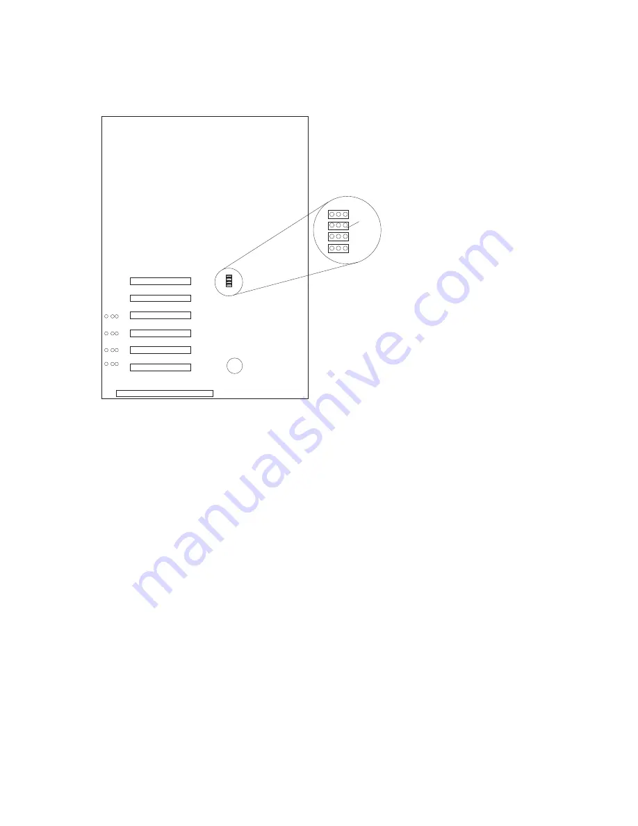
5. Install the jumper extension cable on the Power on control jumper (J32):
a. Note the position of the jumper on the pin block and remove the jumper.
J32
b. Align the white cable with pin 1 and insert the connector over the pin block.
c. If necessary, change the position of the jumper on the jumper extension cable.
Note: The default jumper position of J32 and the jumper extension cable is a jumper on pins 1
and 2. Refer to the “Hardware Information” section of the
IBM Netfinity 5500 M20 Server
Library for a description of the jumper.
d. Route the jumper extension cable along the system board and the shuttle side wall.
18
Processor Upgrade Instructions
Summary of Contents for Netfinity 1000
Page 1: ...IBM Netfinity Four Way Processor Upgrade Kit Installation Instructions...
Page 2: ......
Page 3: ...IBM Netfinity Four Way Processor Upgrade Kit Installation Instructions...
Page 8: ...vi Processor Upgrade Instructions...
Page 43: ......
Page 44: ...IBM Part Number 01K7672 Printed in U S A 1K7672...


