background image


 Trademarks

The following terms are trademarks of the IBM Corporation
in the United States or other countries or both:

The following terms are trademarks of other companies:

9.

C-bus is a trademark of Corollary, Inc

Pentium and MXX are trademarks or registered trademarks
of Intel Corporation.

Microsoft and Windows NT are trademarks or registered
trademarks of Microsoft Corporation.

EduQuest

HelpCenter

HelpClub

HelpFax

IBM

Netfinity

OS/2

PS/1

PS/2

Skill Dynamics

SystemXtra

ThinkPad

Notes

Lotus Development Corporation

142

IBM Netfinity Servers HMM 


Summary of Contents for Netfinity 3500 Series

Page 1: ...S05L 1908 01 IBM Netfinity Servers IBM Netfinity 3500 Type 8644 Models 10U 10X 20U 20X 21U 21X 30U 30X Hardware Maintenance Manual April 1998 We Want Your Comments Please see page 138...

Page 2: ......

Page 3: ...S05L 1908 01 IBM Netfinity Servers IBM Netfinity 3500 Type 8644 Models 10U 10X 20U 20X 21U 21X 30U 30X Hardware Maintenance Manual April 1998 We Want Your Comments Please see page 138 IBM...

Page 4: ...ation herein these changes will be incorporated in new editions of the publication IBM may make improvements and or changes in the product s and or the program s described in this publication at any t...

Page 5: ...g an IBM product be sure to review Safety Information on page 126 Online Support Use the World Wide Web WWW or the IBM PC Company BBS to download Diagnostic BIOS Flash and Device Driver files File dow...

Page 6: ...iv IBM Netfinity Servers HMM...

Page 7: ...Undetermined Problems 38 Locations 49 Symptom to FRU Index 105 Parts Listing 119 Related Service Information 125 Safety Information 126 Battery Notice Lithium 131 Battery Notice Nickel Cadmium 134 Las...

Page 8: ...vi IBM Netfinity Servers HMM...

Page 9: ...es and I O Ports 20 Start Options 21 Date and Time 21 System Security 21 Using the Power On Password Menu 21 Using the Administrator Password Menu 23 Using the Enhanced Security Features 24 Restrictin...

Page 10: ...55 Loading 55 Completing the Installation 56 Connecting External Options 58 Adding a Hot Swap Storage Expansion Enclosure 58 Adding External SCSI Devices 58 Attaching External Options 60 Controls 61 E...

Page 11: ...Write Protect Switch 98 Microprocessor Speed Switches 99 System Board Replacement 100 U Bolt 101 Universal Serial Bus Ports 103 Video Port Connector 104 Symptom to FRU Index 105 No Beep Symptoms 105 B...

Page 12: ...ng any FRUs ensure the latest level of BIOS is installed on the system A down level BIOS might cause false errors and unnecessary replacement of the system board 2 If multiple error codes are displaye...

Page 13: ...rror is pressing the wrong key on the keyboard Notes Some hardware and software errors are caused by configuration conflicts For information on handling these situations see Resolving Configuration Co...

Page 14: ...dependently of the operating system and must be run either from CD or diskette The server diagnostic test programs can identify most problems associated with major components of the server the system...

Page 15: ...e of operation To change the mode to Enhanced select Start Options from the Configuration Setup Utility program menu and follow the prompts on the screen Note The amount of available memory shown migh...

Page 16: ...r conflict is detected by the SCSI subsystem Refer to the SCSI documentation in the ServerGuide package that comes with the server for information about these messages Diagnostic Error Messages Diagno...

Page 17: ...wing 1 Power off the server and any attached devices Note Do not press Ctrl Alt Del 2 Power on all attached devices then power on the server 3 Place the IBM Enhanced Diagnostic CD in the CD ROM drive...

Page 18: ...the passwords at the password prompt However if you think you might need to change any settings in the Configuration Setup Utility program you must type the administrator password at the password prom...

Page 19: ...the menu item then press F1 c When you have finished viewing and changing settings press Esc to return to the Configuration Setup Utility program menu d Before you exit from the program select Save Se...

Page 20: ...e To exit from the Configuration Setup Utility program press Esc and follow the instructions on the screen 12 IBM Netfinity Servers HMM...

Page 21: ...ities of hard disk drives vary by model Server supports up to four internal hard disk drives CD ROM Drive Standard IDE Keyboard and Auxiliary Device Keyboard Three button mouse Expansion Slots Support...

Page 22: ...I One external connector 16 bit One internal connector 16 bit Full duplex 10 100 Mbps Ethernet controller 10BASE T 100BASE TX port Integrated Direct Memory Access DMA Buffer Management Unit for low mi...

Page 23: ...uring the Ethernet Controller on page 28 Ethernet Cable Specifications on page 31 Ethernet Connection Problems on page 34 Ethernet Subsystem Error Messages on page 35 Hard Disk Drive Boot Error 1962 a...

Page 24: ...devices refer to the documentation that comes with the devices for specific information about the appropriate jumper and switch settings The server comes with the following hardware configuration util...

Page 25: ...a convenient way to display and change the settings After you run and exit the Configuration Setup Utility program configuration information is stored in electrically erasable programmable read only m...

Page 26: ...th an administrator and a power on password you can enter either one However to change any settings in the Configuration Setup Utility program you must enter the administrator password If you enter th...

Page 27: ...is a quick reference for identifying symbols in the Configuration Setup Utility program A bullet beside a menu item indicates that an additional menu is available Information enclosed in brackets can...

Page 28: ...recognizes ports from their port assignments Each port must have a unique port assignment The Configuration Setup Utility program normally handles this but you might have special hardware or software...

Page 29: ...time is in a 24 hour format hour minute second The system date is in standard format for your country For example in the United States the format is MM DD YYYY Month Day Year Select Date and Time then...

Page 30: ...not use a power on wakeup or lockout function 3 A serial mouse is not affected by the password prompt Off mode To adjust the server configuration so that the operating system does not display an error...

Page 31: ...ual Press the Left Arrow or Right Arrow key to toggle between selections 5 Select Change Power On Password and follow the instructions on the screen Notes 1 If a power on password is set and then forg...

Page 32: ...CMOS Request Jumper J7E1 on page 97 for further information If enhanced security is enabled you must replace the system board To delete an administrator password 1 Select Administrator Password 2 Sel...

Page 33: ...rity can be enabled or disabled only when you update the system programs in the server 1 Insert a system programs update diskette in the server System programs updates are available on the World Wide...

Page 34: ...memory ROM initialization this feature can be used in conjunction with an administrator password to prevent the use of adapter ROM based utility programs Advanced Setup Select Advanced Setup to change...

Page 35: ...to the server during startup When you install or remove Plug and Play adapters this information is interpreted by the BIOS which supports Plug and Play technology If the required resources are availab...

Page 36: ...ols the power management features of the server and the settings for APM BIOS mode are ignored Refer to the operating system documentation to determine if ACPI is supported To set ACPI BIOS mode 1 Sel...

Page 37: ...rates at a data rate of 100 Mbps that is ten times faster than standard Ethernet However except for the different operating speeds Fast Ethernet and standard Ethernet are structurally identical Applic...

Page 38: ...erver supports To find out which operating systems the server supports go to the following World Wide Web address http www pc ibm com us server If you need additional Ethernet connections you can inst...

Page 39: ...568 Category 5 cable must be used for 10BASE T and 100BASE TX Attention The 10BASE T Ethernet and the 100BASE TX Fast Ethernet cabling in the network must be Category 5 or higher to meet various stand...

Page 40: ...e pairs will be used by the 10BASE T or 100BASE TX network The c represents the velocity of light traveling in a vacuum which is 300000 km sec 186400 mi sec Table 1 Cabling Specifications for 10BASE T...

Page 41: ...ASE T 100 BASE TX 1 2 3 6 4 5 7 8 Pin TD TD RD RD RJ 45 Modular Connector Not used TD TD RD RD Not used Signal Name Signal Name Relative to the device connected to the adapter The following figure ill...

Page 42: ...that the cable is installed correctly 2 Check the Ethernet activity light on the front of the server Note This light is off when you run the diagnostic programs in the Configuration Setup Utility pro...

Page 43: ...edia test failed check the cable Error 105 indicates that a power on diagnostic test performed by the Ethernet module did not execute correctly If this error message appears you must have the server s...

Page 44: ...ed the memory test E61 Service boot startup canceled that is the boot diskette image was not downloaded from the network E62 Cannot initialize controller E63 Cannot initialize controller E67 Cannot in...

Page 45: ...CP timeout M42 No client or server Internet protocol IP address M43 No boot startup file name M44 Cannot ARP redirected BOOTP server M6f System is locked Press Ctrl Alt Del to restart M90 Cannot initi...

Page 46: ...llowing 1 Power off the computer 2 Remove or disconnect the following one at a time until you find the failure power on the computer and reconfigure each time Any external devices Surge suppressor dev...

Page 47: ...Using the operating systems programs format the hard disk drive The drive is defective Replace the hard disk drive Power Supply If the power on indicator is not on the power supply fan is not running...

Page 48: ...system board 1 10 11 20 Pin Signal Function 1 3 3 V 3 3 V dc 2 3 3 V 3 3 V dc 3 COM Ground 4 5 V 5 V dc 5 COM Ground 6 5 V 5 V dc 7 COM Ground 8 POK Power Good 9 5VSB Standby Voltage 10 12 V 12 V dc...

Page 49: ...tion Setup Utility program configures only the system hardware and interrupt requests The program does not consider the requirements of the operating system or the application programs For these reaso...

Page 50: ...ses that are used by the system board functions The best way to resolve memory address conflicts is to change the addresses that are used by the application program or the device driver You can use th...

Page 51: ...e SCSI controller is 7 Do not change this value SCSI Parity Checking The default value is Enabled Do not change this value Host Adapter SCSI Termination The default value is Low On High On Do not chan...

Page 52: ...and watch the SCSISelect messages as each drive spins up After the drive that you want to view or format spins up press Ctrl A Unexpected SCSI Command Failure Target SCSI ID 4 SCSI CDB Sent 3 E 7 2 H...

Page 53: ...curity features can help to protect the server data and programs from unauthorized access and use and help to physically protect the server from theft and tampering To control access to the informatio...

Page 54: ...e Configuration Setup Utility program If the system programs do not update the settings you can use the Configuration Setup Utility program to reconfigure the appropriate settings For example when you...

Page 55: ...nt Air temperature System on 10 to 35 C 50 to 95 F at altitude 0 915 m 3000 ft 10 to 32 C 50 to 90 F at altitude 915 2134 m 3000 7000 ft System off 10 to 43 C 50 to 110 F Humidity System on 8 to 80 Sy...

Page 56: ...with ISO 9296 Actual sound pressure levels in your location might exceed the average values stated because of room reflections and other nearby noise sources The declared sound power levels indicate...

Page 57: ...on page 63 Feet Stabilizing on page 64 Internal Drives on page 65 Input Output Connectors on page 78 Keyboard and Mouse Connectors on page 80 Memory Modules on page 81 Microprocessors on page 83 Para...

Page 58: ...ocated on the rear of the server see Input Output Connectors on page 78 for an illustration The server system board contains two 16 bit ISA bus expansion slot connectors and four 32 bit PCI bus expans...

Page 59: ...apters Notes See Input Output Connectors on page 78 for an illustration of the expansion slots on the rear of the server If you remove an adapter be sure to reassign the system resources as available...

Page 60: ...ll the adapter a Carefully grasp the adapter and align it with the expansion slot Note When installing full length adapters in slots 3 through 6 align the end of the adapter with the card guide on the...

Page 61: ...the administrator password set switch 7 as shown in the following illustration It might be helpful to use the end of a small screwdriver to set the switch Administrator Password Locked Administrator...

Page 62: ...gure the system and reset the system date and time CD ROM Drive An IDE CD ROM drive is a standard feature on all Netfinity 3500 servers CD ROM drives can play back or read from a CD but cannot write i...

Page 63: ...drive Do not manually force the tray open 2 Place the CD in the tray with the label facing up 3 Close the tray by pressing the Eject Load button or by gently pushing the tray forward When the tray is...

Page 64: ...that no tools or loose screws are left inside the server 2 Clear any cables that might impede the replacement of the cover 3 Install the side cover a Align the top and bottom cover tabs with the corre...

Page 65: ...one line to the wall outlet and the server and plug the power cords into properly grounded electrical outlets If you are in the United Kingdom plug in the power cords first then connect the telephone...

Page 66: ...stallation Adding a Hot Swap Storage Expansion Enclosure The ibm hardware is one of several SCSI storage enclosures that you can attach to the server You can connect the storage enclosure to the exter...

Page 67: ...er do not exceed 6 meters 19 7 feet total length for all cables If you connect four or less UltraSCSI devices to the UltraSCSI controller do not exceed 1 meter 3 3 feet total length for all cables Att...

Page 68: ...ns To attach an external option 1 Power off the server and all attached devices 2 Follow the instructions that come with the option and the information in this chapter to connect it to the server 60 I...

Page 69: ...ingle touch of the power switch will not turn off the power If power must be turned off during POST press and hold the power switch for 5 seconds or disconnect the power cord After POST the power swit...

Page 70: ...must be Category 5 or higher to meet various standards including electromagnetic compatibility See Configuring the Ethernet Controller on page 28 for additional information about the Ethernet controll...

Page 71: ...er to set the switch Note In the following illustration MAC represents media access control This refers to the Ethernet controller address Ethernet Normal Operation Ethernet MAC Disabled 1 2 3 4 5 6 7...

Page 72: ...eet a quarter turn away from the server Then carefully position the server on its feet When you need to access the inside of the server to install options you might find it easier to place the server...

Page 73: ...erver comes with an integrated drive electronics IDE CD ROM drive Open Bays The server s design accommodates 3 5 inch and 5 25 inch devices such as hard disk tape and rewritable optical disk drives Th...

Page 74: ...cations Table 4 describes some of the drive types that you can install in each bay and their width and height requirements Table 4 Maximum Allowable Drive Sizes Bays Drive Widths Drive Types Drive Hei...

Page 75: ...ble is connected to the 68 pin Channel A SCSI connector on the system board This cable provides four connectors for attaching other internal SCSI devices For correct termination see Termination Requir...

Page 76: ...ive is the primary device If you install a second IDE device it must be the secondary device To attach an external SCSI drive you must install an appropriate adapter in the server SCSI Drives Note Any...

Page 77: ...UN If a physical device supports no logical devices its LUN is 0 Most SCSI devices support only LUN 0 Certain types of physical SCSI devices bridge controllers can support more than one logical device...

Page 78: ...ion 1 Remove the server cover see Side Access Cover on page 94 2 Choose the bay in which you want to install the drive Refer to Table 4 on page 66 for the drive types and sizes available for each bay...

Page 79: ...y the tab on the left edge of the panel as shown b Remove the top cover by using a flat blade screwdriver to release the tab on the left edge as shown c Disconnect the power and signal cables attached...

Page 80: ...acket b Lower the front of the drive bracket lift up on the rear and slide it out c If necessary disconnect the power and signal cables attached to the drives in the lower drive bracket d Continue wit...

Page 81: ...a tray is attached to a drive that you intend to install you must remove the tray before installing the drive Follow the instructions in the documentation that comes with the drive 6 Using the instru...

Page 82: ...ctors are facing the rear of the server Align the screw holes then insert and tighten the four screws 11 Reinstall the upper drive bracket and secure it with screws at the top and bottom 12 Reconnect...

Page 83: ...6 1 Read Termination Requirements on page 69 2 Remove the server cover see Side Access Cover on page 94 3 Remove the lower drive bracket as described in step 4 on page 72 4 Touch the static protective...

Page 84: ...ay use the screws that come with the preinstalled drive 2 If you are installing a drive in bay 5 turn the drive upside down before you slide it into the bay This ensures that the drive connector will...

Page 85: ...u disconnected in step 4c on page 72 9 To install a drive in bays 1 through 4 go to Installing or Removing Drives in Bays 1 through 4 on page 73 10 If you want to install or remove any other options d...

Page 86: ...B Connectors Attach I O devices with universal serial bus USB connectors to USB connector 1 and connector 2 You need a 4 pin cable to connect a device to these ports Parallel Connector A signal cable...

Page 87: ...is no playback capability through the internal speaker Ethernet Connector An unshielded twisted pair UTP cable with an RJ 45 connector attaches here to the 10 100 Ethernet controller on the system boa...

Page 88: ...e a mouse or other pointing device 6 4 2 1 3 5 Table 5 shows the pin number assignments for the keyboard and auxiliary device port connectors Table 5 Keyboard and Auxiliary Device Port Connectors Pin...

Page 89: ...install them in adjacent connectors with no vacant memory connectors in between If you are installing DIMMs of different sizes install the DIMMs with greater memory capacity starting with the connecto...

Page 90: ...tents of this table and additional information can be found on a label located inside the server Again alternate configurations are possible Note The values in Table 6 are represented in megabytes MB...

Page 91: ...can distribute the processing load between microprocessors This can enhance performance for database and point of sale applications integrated manufacturing solutions and other applications The voltag...

Page 92: ...microprocessor the server operation might be unreliable To prevent this use a microprocessor with the same internal and external clock speed and the same cache size and voltage requirements as those...

Page 93: ...find the configuration switches section of the system board illustration See System Board on page 96 To install a microprocessor 1 Remove the server cover see Side Access Cover on page 94 2 If the se...

Page 94: ...ndary on the system board See the illustration in System Board on page 96 b Place your index fingers on the small retainer tabs on the top of the microprocessor Push in toward the microprocessor until...

Page 95: ...essor to any unpainted metal surface in the server then remove the new microprocessor 8 Press in on the retainer tabs until they click Note For the location of the retainer tabs see the illustration i...

Page 96: ...oprocessor in the server you must reconfigure the server Follow the procedure described in Configuration Setup Utility Program Menus on page 19 You might also need to make changes to the operating sys...

Page 97: ...l Port EPP Extended Parallel Port ECP Table 7 shows the pin number assignments for the parallel port connector The signal names for all three modes are shown SSP and ECP signal names are the same EPP...

Page 98: ...ery Mode 1 2 3 4 5 6 7 8 1 2 3 4 5 6 7 8 ON ON OFF OFF 3 Move the switch to the ON position 4 Insert the POST BIOS update flash diskette into drive A 5 Turn on the server 6 After the update session co...

Page 99: ...ed in the server The external SCSI cable provides a connector to which you can attach an external SCSI device Table 8 shows the pin number assignments for the 68 pin SCSI connectors Table 8 The 68 Pin...

Page 100: ...Assignments 92 IBM Netfinity Servers HMM...

Page 101: ...ts transmit and receive data and commands at a rate of 300 bits per second bps up to 115200 bps The bits per second measurement is commonly referred to as the baud rate Both of the serial connectors o...

Page 102: ...ing 1 If necessary unlock the server side cover 2 Remove the side cover by pulling out on the cover release tab at the rear of the side cover Then slide the cover toward the front of the server and li...

Page 103: ...on when the server is accessing a SCSI hard disk drive If this light remains illuminated it might indicate that either the SCSI bus or the system microprocessor has stopped Ethernet Activity Light Com...

Page 104: ...hannel A SCSI connector 68 pin 1 Channel B SCSI connector 50 pin 11 Channel B SCSI connector 68 pin 12 Clear CMOS Request password jumper J7E1 13 Configuration switches 14 Battery 15 RAIDport connecto...

Page 105: ...jumper To reset CMOS do the following 1 Locate the Clear CMOS Request jumper J7E1 on the system board 2 Move the jumper from its normal position pins 1 and 2 to pins 2 and 3 It might be helpful to use...

Page 106: ...using a diskette drive Note This switch does not affect the ability to read information from a diskette 1 Locate the configuration switches on the system board 2 For normal diskette operation or for...

Page 107: ...to the label inside the server or see System Board on page 96 2 To set the appropriate microprocessor speed set switches 1 to 4 as shown in the following illustration It might be helpful to use the e...

Page 108: ...atest level of BIOS for the system you are servicing must be installed on the new system board To do this you must run the Flash Update program using the Flash Update diskette shipped with the new sys...

Page 109: ...Insert the U bolt through the rear panel then attach and tighten the nuts with an appropriately sized or adjustable wrench 4 If you have completed installing the U bolt and do not want to install any...

Page 110: ...e U bolt and around an object that is not a part of or permanently secured to the building structure or foundation and from which it cannot be removed then fasten the cable ends together with a lock 1...

Page 111: ...nnector into multiple attachment points A hub has multiple ports where peripherals can be attached USB provides 12 megabits per second Mbps bandwidth with a maximum of 63 peripherals and a maximum sig...

Page 112: ...rt Connector Pin Number Assignments Pin Signal 1 Red 2 Green or monochrome 3 Blue 4 Not connected 5 Ground 6 Red ground 7 Green ground or monochrome ground 8 Blue ground 9 Reserved 10 Ground 11 Not co...

Page 113: ...servicing the computer XX used in place of the last 2 digits can be any number or letter No Beep Symptoms No Beep Symptom FRU Action No Beeps occur after successfully completing POST 1 Disconnected sp...

Page 114: ...1 Dual Inline Memory Module 2 Microprocessor 3 System Board 1 4 3 Interrupt vector loading test has failed 1 System Board 2 Microprocessor 2 1 1 Secondary DMA register test is in progress or has faile...

Page 115: ...Setup One Beep POST completed successfully or an incorrect password was entered 1 N A Two Short Beeps POST encountered an error 1 Run Diagnostics Three Short Beeps 1 Dual Inline Memory Module 2 Micro...

Page 116: ...ware error 1 Run Diagnostics 2 System Board 151 Real time clock failure 1 Run Diagnostics 2 Battery 3 System Board 161 Real time clock battery failure 1 Battery 162 A change in device configuration oc...

Page 117: ...n Configuration Setup 186 System Board or security hardware problem 1 Run Configuration Setup 2 System Board 187 Administrator password and boot sequences have been cleared see POST error 162 1 See PO...

Page 118: ...secondary IDE device error 1 Run diagnostics 2 Hard Disk Drive 3 Primary or Secondary IDE Device 1800 PCI adapter interrupt request error 1 Run Configuration Setup 2 Run EISA Configuration 3 Failing...

Page 119: ...ram 1853 Plug and Play adapter memory request error see Configuration Setup Utility Program Menus on page 19 Adapters on page 50 1 Verify all adapter settings in the Configuration Setup Utility progra...

Page 120: ...Card 4 System Board 01A2h Failed 486 Instruction test 1 Processor 2 System Board 01A3h Failed 386 Instruction test 1 Processor 2 System Board 01A4h Failed 386 Register test 1 Processor 2 System Board...

Page 121: ...stem continues to bypass the CD ROM drive 1 CD ROM Diskette drive in use light stays on or the system bypasses the diskette drive 1 Verify that the diskette drive is enabled in the Configuration Setup...

Page 122: ...the Configuration Setup Utility program Screen flickers Attention Using a resolution or refresh rate that is not supported by the monitor might damage it 1 Set monitor to highest noninterlaced refresh...

Page 123: ...to powering on the system 1 Check all cable connections 2 For SCSI options check for proper termination 3 Option Device The parallel port cannot be accessed or the number of parallel ports displayed i...

Page 124: ...er Card The Ethernet Adapter cannot connect to the network See Ethernet Connection Problems on page 34 1 Ethernet Adapter The Configuration Setup Utility program reports the Ethernet controller interr...

Page 125: ...r 10 Mbps or 100 Mbps The Ethernet Activity light does not come on 1 Make sure the network device drivers are loaded 2 Check all connections 3 Try sending data from this workstation 4 Use another Ethe...

Page 126: ...connector at the hub or switch 3 The network device driver files might be missing or corrupted 4 Ethernet Adapter SCSI Messages Message Description All One or more of the following might be causing th...

Page 127: ...Parts Listing 1 2 3 4 5 7 8 9 10 11 12 13 14 15 16 17 18 19 20 6 22 23 24 25 21 IBM Netfinity 3500 Type 8644 119...

Page 128: ...0U 10X 20U 20X 21U 21X 30U 30X 76H2697 4 9 1 GB Hard Disk Drive Half high Models 10U 10X 20U 20X 21U 21X 30U 30X 76H2698 5 1 44 MB Diskette Drive Black Models 10U 10X 20U 20X 21U 21X 30U 30X 75H9550 6...

Page 129: ...5 25 Inch DASD Bracket Models 10U 10X 20U 20X 21U 21X 30U 30X 12J4501 21 EMC Kit Models 10U 10X 20U 20X 21U 21X 30U 30X 12J4508 22 330 Watt Power Supply Models 10U 10X 20U 20X 21U 21X 30U 30X 01K9866...

Page 130: ...ve Bezel 1 each 12J5551 Miscellaneous Screw Kit Models 10U 10X 20U 20X 21U 21X 30U 30X 93F0041 Mouse Models 10U 10X 20U 20X 21U 21X 30U 30X 76H6620 Power Cord Models 10U 10X 20U 20X 21U 21X See Power...

Page 131: ...02K0879 Hebrew 02K0880 Hungarian 02K0881 Icelandic 02K0882 Italian 02K0883 Japan 02K0899 Latin Spanish 02K0867 Norwegian 02K0884 Polish 02K0885 Portuguese 02K0886 Romania 02K0887 Russian 02K0888 Serbi...

Page 132: ...rmany 1339520 Hungary 1339520 Israel 14F0087 Italy 14F0069 Latvia 1339520 Netherlands 1339520 Norway 1339520 Poland 1339520 Portugal 1339520 Serbia 1339520 Slovakia 1339520 South Africa 14F0015 Spain...

Page 133: ...upplement and the PS 2 Hardware Maintenance Manual part number 83G8990 form number S52G 9971 02 Safety Information 126 General Safety 126 Electrical Safety 127 Safety Inspection Guide 128 Handling Ele...

Page 134: ...tomer s personnel are not in a hazardous position Place removed covers and other parts in a safe place away from all personnel while you are servicing the machine Keep your tool case away from walk ar...

Page 135: ...switch or electrical outlet If an electrical accident occurs you can then operate the switch or unplug the power cord quickly Do not work alone under hazardous conditions or near equipment that has h...

Page 136: ...tive surface of a plastic dental mirror The surface is conductive such touching can cause personal injury and machine damage Do not service the following parts with the power on when they are removed...

Page 137: ...the power cord for a A third wire ground connector in good condition Use a meter to measure third wire ground continuity for 0 1 ohm or less between the external ground pin and frame ground b The powe...

Page 138: ...part from touching your clothing Most clothing is insulative and retains a charge even when you are wearing a wrist strap Use the black side of a grounded work mat to provide a static free work surfa...

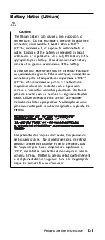
Page 139: ...a 100 C 212 F n o a incinere ou ponha o conte do da respectiva c lula em contacto com a gua nem remova o respectivo conector polarizado Destrua a pilha de acordo com as normas ou regulamenta es locai...

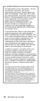
Page 140: ...teni polariz lt csatlakoz j b l elt vol tani sz tszedni 100 C 212 F feletti h m rs kletre felhev teni el getni vagy az elem cell j nak tartalm t nedvess g hat s nak kitenni Az elem megsemmis t s nek a...

Page 141: ...predpisov a pravidiel Pou ite iba v robcom odpor an bat riu Pou itie nevhodnej bat rie m e zapr ini vznietenie alebo v buch bat rie La bateria de repuesto es una bateria de litio y puede provocar inc...

Page 142: ...ez pas ne les exposez ni au feu ni l eau Ne les mettez pas en court circuit Pour les mettre au rebut conformez vous la r glementation en vigueur Lorsque vous remplacez la pile de sauvegarde ou celle d...

Page 143: ...la batteria di supporto utilizzare soltanto i tipi inseriti nell appropriato Catalogo parti L impiego di una batteria non adatta potrebbe determinare l incendio o l esplosione della batteria stessa Ni...

Page 144: ...ts When a CD ROM drive is installed note the following CAUTION Use of controls or adjustments or performance of procedures other than those specified herein might result in hazardous radiation exposur...

Page 145: ...iretamente por meio de instrumentos ticos e evite exposi o direta com o feixe de luz Rayonnement laser si carter ouvert vitez de fixer le faisceau de le regarder directement avec des instruments optiq...

Page 146: ...complete it and then fax it to IBM HMM Survey at 919 543 8167 USA Name Phone Number 1 Do you like this manual Yes No 2 What would you like to see added changed or deleted in this manual 3 What is your...

Page 147: ...Diskette Version Type and version level Hardware configuration Print print screen configuration currently in use BIOS level Operating system software Type and version level Important To eliminate con...

Page 148: ...080 IBM Warranty Parts Claims Center Number Information 919 517 0001 Bulletin Board Service PC Company 800 426 8322 Customer Education Business Unit 800 999 0052 Customized Operational Services 800 23...

Page 149: ...PartnerLine 800 263 2769 Parts Orders Exchange or Emergency 416 443 5808 Fax Parts Regular Orders Exchange 416 443 5755 Parts Orders Inquiries 514 938 3022 PC Co Bulletin Board Montreal 905 316 4255 P...

Page 150: ...C bus is a trademark of Corollary Inc Pentium and MXX are trademarks or registered trademarks of Intel Corporation Microsoft and Windows NT are trademarks or registered trademarks of Microsoft Corpor...

Page 151: ......

Page 152: ...IBM Part Number 10L9833 Printed in U S A S 5L 19 8 1...

Reviews: