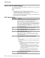
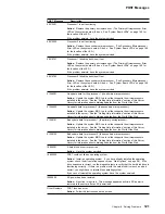
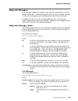

POST Messages
POST Message
Description
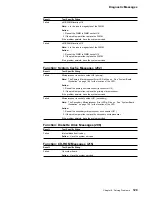
176
177
178
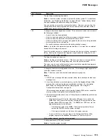
A security hardware error occurred.
Action: Check for indications that someone has tampered with the server. If no
one has tampered with the server, have the system serviced.
184
The power-on password information stored in your server has been removed.
Action: From the Configuration/Setup Utility program main menu, select System
Security. Then, follow the instructions on the screen. For information about using
the Configuration/Setup utility programs, see “Using the Configuration/Setup Utility”
on page 22.
If this information cannot be restored, have the system serviced.
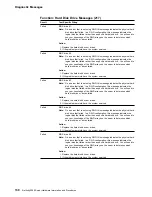
185
A power failure damaged the stored information about the drive-startup sequence.
Action: From the Configuration/Setup Utility program main menu, select Start
Options; then, follow the instructions on the screen. For information about using
the Configuration/Setup utility programs, see “Using the Configuration/Setup Utility”
on page 22.
If this information cannot be restored, have the system serviced.
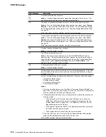
186
A system board or hardware error occurred.
Action: Have the system serviced.
187
The VPD serial number is not set.
Action: The system serial number is set in the VPD EEPROM at the time of
manufacturing. If the system board has been replaced, the system serial number
will be invalid and should be set. From the main menu of the Configuration/Setup
Utility program, select System Information, then select Product Data. If the
problem persists, have the system serviced.
188
A vital product data (VPD) error occurred.
Action: Have the system serviced.
189
An attempt has been made to access the server with invalid passwords. After three
incorrect attempts, the server locks up; that is, the logon data fields are no longer
available to the user.
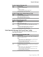
201
An error occurred during the memory controller test. This error can be caused by:
Incorrectly installed memory
A failing memory module
A processor-board problem
A system board problem
Action:
1. If you just installed memory, see “Installing or Removing Memory Modules” on
page 54 to verify that the new memory is correct for your server. Verify that the
memory modules are installed and seated correctly.
2. If the problem persists, check to see if the system has isolated the problem to a
memory module:
If the System Error LED on the information LED panel is on, check the
DIMM Error LEDS next to the memory sockets on the system board (see
“System Board LEDs” on page 168). If a DIMM Error LED is on, run the
diagnostic program for the memory.
If the tests fail, replace the DIMM. If the problem persists after you replace
the DIMM, have the system serviced.
If the memory tests do not fail, have the system serviced.
3. If no error LED is on, the error logs in the Configuration/Setup Utility program
might provide additional information on the memory error.
If the problem persists, have the system serviced.
116
Netfinity 5000 Server Hardware Information and Procedures