background image


Appendix A. Help and service information

During the warranty period, you can get toll-free technical support 24 hours a day, 7 days a week

1

 to

answer questions about your upgrade kit (toll-free technical support is available in the United States,
Puerto Rico, and Canada only). If you need warranty service, return or exchange is available. In addition,
you might be entitled to service at your location. Your technical support representative can help you
determine the best alternative.

Before calling, please prepare for your call by following these steps.

 Step 1: Troubleshooting

1. Remove and reattach all cables.

2. Inspect the upgrade kit components for any damage.

3. Retrace all steps in the upgrade kit instructions.

Step 2: Preparing for the service call

To assist the technical support representative, have the following information available:

1. Option name and description

2. Proof of purchase

3. Server model, serial number, and the documentation that comes with your server.

4. Exact wording of the error message (if any)

5. Description of the problem

6. Hardware and software configuration information for your system

If possible, be at your server. Your technical support representative might want to walk you through the
problem during the call.

Step 3: Placing the service call to IBM

Use one of the following numbers:

Ÿ

In the United States and Puerto Rico, call 1-800-772-2227.

Ÿ

In Canada, call 1-800-565-3344.

Ÿ

In all other countries, contact your IBM reseller, IBM marketing representative, or your place of
purchase.

1

Response time will vary depending on the number and nature of calls received.

26 

 Copyright IBM Corp. 1999

Summary of Contents for Netfinity Series

Page 1: ...IBM Netfinity Four Way Processor Upgrade Kit Installation Instructions ...

Page 2: ......

Page 3: ...IBM Netfinity Four Way Processor Upgrade Kit Installation Instructions ...

Page 4: ... are periodically made to the information herein these changes will be incorporated in new editions of the publication IBM may make improvements and or changes in the product s and or the program s described in this publication at any time This publication was developed for products and services offered in the United States of America IBM may not offer the products services or features discussed i...

Page 5: ... upgrade installation 21 Updating the system configuration 21 Updating the system diagnostic programs 22 Updating the advanced system management processor code 23 Troubleshooting 25 Appendix A Help and service information 26 Step 1 Troubleshooting 26 Step 2 Preparing for the service call 26 Step 3 Placing the service call to IBM 26 Appendix B Product warranties and notices 27 Warranty Statements 2...

Page 6: ...nweisen lesen Installálás előtt olvassa el a Biztonsági előírások kézikönyvét Prima di installare questo prodotto leggere l opuscolo contenente le informazioni sulla sicurezza Lees voordat u dit product installeert eerst het boekje met veiligheidsvoorschriften Les heftet om sikkerhetsinformasjon Safety Information før du installerer dette produktet Przed zainstalowaniem tego produktu należy przecz...

Page 7: ...n possible use one hand only to connect or disconnect signal cables Never turn on any equipment when there is evidence of fire water or structural damage Disconnect the attached power cords telecommunications systems networks and modems before you open the device covers unless instructed otherwise in the installation and configuration procedures Connect and disconnect cables as described in the fo...

Page 8: ...vi Processor Upgrade Instructions ...

Page 9: ... provider for assistance Before you begin Read through these instructions to familiarize yourself with the installation procedure Be sure you have the additional microprocessors and memory options required to complete the upgrade see Required companion options on page 2 The option contains the following items Processor housing assembly consisting of Processor housing Processor board Memory board T...

Page 10: ...rrection ECC registered dual inline memory module DIMM 256 MB registered SDRAM ECC DIMM 512 MB registered SDRAM ECC DIMM A combination of the 128 MB 256 MB and 512 MB registered SDRAM ECC DIMMs For more information about the memory configurations supported see Installing memory module kits on page 14 3 Optionally you can install a second 500 watt power supply for redundant power With a redundant p...

Page 11: ...service code 33 using the appropriate completion status machine type and serial number Use TA tac code L01 and action code 4 for the installation Use the appropriate TA and action code if you experience problems Record other B O as 990 and enter the MES number of 866UPG in the MES field requires a six digit number IBM business partners authorized to provide warranty service can be reimbursed for i...

Page 12: ... M20 BIOS Update Diskette in the diskette drive 2 Press Ctrl Alt Del to restart your server The system begins the power on self test POST 3 Select 1 Update POST BIOS from the menu that contains various flash update options 4 Select Y when you are asked if you would like to move the current POST BIOS image to the backup ROM location Important The backup image of the current POST BIOS is helpful wit...

Page 13: ... also might have more than one power cord To remove all electrical current from the device ensure that all power cords are disconnected from the power source 1 2 3 If you are in the United Kingdom and have a modem or fax machine attached to your server you must disconnect the telephone line from the server before unplugging any power cords also known as power cables When reassembling your server y...

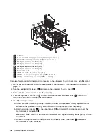
Page 14: ... of the shuttle 10 Slide the shuttle 2 to the rear of the server 11 Remove the power supply cables from the rear of the processor housing 12 Remove the four screws 1 securing the processor housing 13 If the processor housing has two levers at the top corners pull the levers up 6 Processor Upgrade Instructions ...

Page 15: ...nd in a safe place for use in troubleshooting the upgrade if troubleshooting becomes necessary 15 Note the location of all cables connected to the shuttle and disconnect the cables 16 Remove the shuttle from the server and place it on a flat static free surface 17 Go to Replacing the diagnostic panel and front panel assemblies on page 8 Upgrade installation 7 ...

Page 16: ...Install the diagnostic panel assembly that comes with this option Connect the cable and secure the diagnostic panel assembly with screws 2 Replace the front panel assembly 4 a Disconnect the cable 6 and remove the screws 5 that secure the front panel assembly b Remove the front panel assembly from the server c Carefully position the front panel assembly that comes with this option d Connect the ca...

Page 17: ...l the handle on the power supply then slide the power supply out of the chassis c Repeat this procedure if a second power supply is installed 3 Loosen the five screws 2 disconnect all power cables and remove the power backplane 1 4 Install the power backplane contained in this option a Lower the power backplane with the power supply connectors toward the rear of the server b Seat the power backpla...

Page 18: ...th this option a Secure the handle to the power supply with screws b Place the handle 4 on the power supply in the open position and slide the power supply into the chassis c Close the handle on the power supply to seat the power supply in the bay d Repeat this procedure if a second power supply is installed 7 If you are not installing a second power supply attach the filler panel over the open ba...

Page 19: ... 1 J13 VRM 2 J14 VRM 3 J16 VRM 4 J17 VRM 5 J18 VRM 6 Installed Installed Installed Installed Three Microprocessors Installed in J1 J2 and J4 J12 VRM 1 J13 VRM 2 J14 VRM 3 J16 VRM 4 J17 VRM 5 J18 VRM 6 Installed Installed Installed Installed Installed Four Microprocessors Installed in J1 J2 J3 and J4 J12 VRM 1 J13 VRM 2 J14 VRM 3 J16 VRM 4 J17 VRM 5 J18 VRM 6 Installed Installed Installed Installed...

Page 20: ...ners 2 and remove the processor housing cover 1 3 Pull on the fasteners and remove the fan assembly 4 If the microprocessor connector 9 contains a microprocessor terminator card 1ð remove the terminator card from the microprocessor connector 5 Install the microprocessor a Touch the static protective package containing the new microprocessor to any unpainted metal surface on the processor housing t...

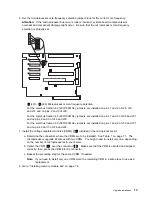
Page 21: ...0 For the core bus fraction 5 0 500 100MHz jumpers are installed on pins 1 and 2 of J30 and J31 and on pins 2 and 3 of J28 and J29 7 Install the voltage regulator modules VRMs 12 included in the microprocessor kit a Determine the connectors where the VRMs are to be installed See Table 1 on page 11 The microprocessor upgrade kit comes with two VRMs You might need to install only one depending on th...

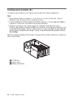
Page 22: ...performance 3 Installing or removing memory modules changes the configuration information in the server Therefore after installing or removing a DIMM you must save the new configuration information in the Configuration Setup program When you restart the server the system displays a message indicating that the memory configuration has changed Start the Configuration Setup Utility program and select...

Page 23: ... 3 and remove the memory board 2 from the server c Place the memory board on a static protective surface such as the static protective package in which the option came 2 Locate the memory module connectors on the memory board Determine the memory module connector into which you will install the memory module 3 Touch the static protective package containing the memory module kit to any unpainted me...

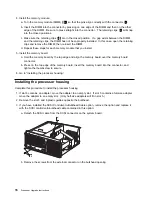
Page 24: ...nd align the memory board over the memory board connector b Press on the top edge of the memory board insert the memory board into the connector and tighten the thumbscrew to secure 6 Go to Installing the processor housing Installing the processor housing Complete this procedure to install the processor housing 1 If slot 6 contains an adapter move the adapter to an empty slot If slot 5 contains a ...

Page 25: ...he external connector tighten the screws 4 Optionally install the RS 485 cable Note Only models with either 01K7234 or 28L1019 as the system board assembly part number support the RS 485 cable option The system board assembly part number is located near the battery on the system board a Connect the RS 485 cable to the RS 485 connector J27 2 on the system board b Insert the external connector into ...

Page 26: ...n block c If necessary change the position of the jumper on the jumper extension cable Note The default jumper position of J32 and the jumper extension cable is a jumper on pins 1 and 2 Refer to the Hardware Information section of the IBM Netfinity 5500 M20 Server Library for a description of the jumper d Route the jumper extension cable along the system board and the shuttle side wall 18 Processo...

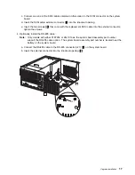
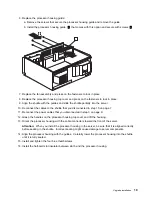
Page 27: ...p 15 on page 7 11 Reconnect the power cables that you disconnected in step 3 on page 9 12 Grasp the handles on the processor housing top cover and lift the housing 13 Orient the processor housing with the cable connectors toward the front of the server Attention When you install the processor housing in the server be sure that it is aligned correctly before seating in the shuttle Incorrect seating...

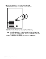
Page 28: ...ystem service label on the inside of the top cover 21 Place one upgrade sticker near the machine type serial number on the information label The upgrade sticker identifies the server as having this option installed Note The information label is located at the front of the server behind the media bay trim bezel 22 Place the other upgrade sticker on the front bezel above the machine type serial numb...

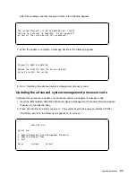
Page 29: ...tion and installing the necessary software for this processor upgrade Updating the system configuration Complete this procedure 1 Connect the power cord to the power supply 2 Connect all other server and device cables and connectors 3 Turn the server power on 4 Watch the monitor screen The system automatically accesses the Configuration Setup program 5 Select Save Settings and exit the Configurati...

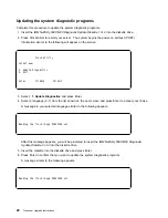
Page 30: ...ate Diagnostics and press Enter 4 Select a language 0 7 from the list shown on the next screen and press Enter to accept your choice A message in your selected language similar to the following appears à ð Reading the flash image ðð21ððð us1 á ñ After this message appears you will be prompted to insert the IBM Netfinity 5500 M20 Diagnostic Update Diskette 2 of 2 into the diskette drive 5 Insert th...

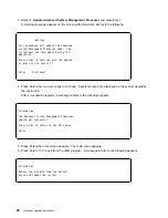
Page 31: ...ting the advanced system management processor code Updating the advanced system management processor code Complete this procedure to update your advanced system management processor code 1 Insert the IBM Netfinity 5500 M20 Advanced System Management Processor Firmware Update Diskette into the diskette drive 2 Press Ctrl Alt Del to restart your server The system begins the power on self test POST I...

Page 32: ...ress Enter when you are ready to continue Several screens are displayed as the system upgrades the microcode After a successful upgrade a message similar to the following appears à ð Information The Advanced System Management Processor update was successful Press Enter to return to the main menu Enter á ñ 5 Press Enter when this screen appears The main menu appears 6 Press Enter or F3 to exit from...

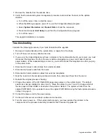
Page 33: ...sembling your server you must reconnect the telephone line after you plug in the power cords 4 Disconnect all power cords cables from electrical outlets 5 Disconnect all power cords from the server 6 Disconnect all communication cables from external receptacles 7 Note the location of the remaining cables and cords then disconnect them from the server 8 Reinstall the original processor housing 9 Ch...

Page 34: ...uctions Step 2 Preparing for the service call To assist the technical support representative have the following information available 1 Option name and description 2 Proof of purchase 3 Server model serial number and the documentation that comes with your server 4 Exact wording of the error message if any 5 Description of the problem 6 Hardware and software configuration information for your syste...

Page 35: ...anty service information Some IBM Machines are eligible for On site warranty service depending on the country where service is performed The IBM Warranty for Machines IBM warrants that each Machine 1 is free from defects in materials and workmanship and 2 conforms to IBM s Official Published Specifications The warranty period for a Machine is a specified fixed period commencing on its Date of Inst...

Page 36: ...ore IBM or your reseller exchanges a Machine or part you agree to remove all features parts options alterations and attachments not under warranty service You also agree to 1 ensure that the Machine is free of any legal obligations or restrictions that prevent its exchange 2 obtain authorization from the owner to have IBM or your reseller service a Machine that you do not own and 3 where applicabl...

Page 37: ...s Date of Installation The date on your sales receipt is the Date of Installation unless IBM or your reseller informs you otherwise During the warranty period IBM or your reseller if approved by IBM to provide warranty service will provide repair and exchange service for the Machine without charge under the type of service designated for the Machine and will manage and install engineering changes ...

Page 38: ... to your facilities to permit them to fulfil their obligations and d inform IBM or your reseller of changes in a Machine s location IBM is responsible for loss of or damage to your Machine while it is 1 in IBM s possession or 2 in transit in those cases where IBM is responsible for the transportation charges Neither IBM nor your reseller is responsible for any of your confidential proprietary or p...

Page 39: ...s Act 1993 or other legislation which cannot be excluded or limited The Consumer Guarantees Act 1993 will not apply in respect of any goods which IBM provides if you require the goods for the purposes of a business as defined in that Act Limitation of Liability The following is added to this Section Where Machines are not acquired for the purposes of a business as defined in the Consumer Guarantee...

Page 40: ...t as expressly provided in these terms and conditions all statutory conditions including all warranties implied but without prejudice to the generality of the foregoing all warranties implied by the Sale of Goods Act 1893 or the Sale of Goods and Supply of Services Act 1980 are hereby excluded Limitation of Liability The following replaces items one and two of the first paragraph of this Section 1...

Page 41: ...subject of the claim or which otherwise gives rise to the claim The following item is added to this paragraph 3 breach of IBM s obligations implied by Section 12 of the Sale of Goods Act 1979 or Section 2 of the Supply of Goods and Services Act 1982 Applicability of suppliers and resellers unchanged The following is added to the end of this Section IBM s entire liability and your sole remedy wheth...

Page 42: ...nction with other products except those expressly designated by IBM are the responsibility of the user IBM may have patents or pending patent applications covering subject matter in this document The furnishing of this document does not give you any license to these patents You can send license inquiries in writing to IBM Director of Licensing IBM Corporation North Castle Drive Armonk NY 10504 178...

Page 43: ......

Page 44: ...IBM Part Number 01K7672 Printed in U S A ð1K7672 ...

Reviews: