IBM NetVista
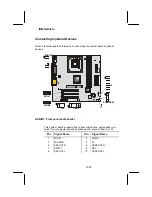
Connecting Optional Devices
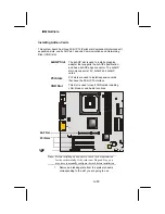
Refer to the following for information on connecting the system board’s optional
devices:
CPUFAN1
P
F
AN1
CAS
F
AN1
DI
M
M
1
DIMM3
DIMM2
ID
E
2
AT
X
1
AT
X
2
AT
X
3
CD
IN
1
AGP1
PCI1
PCI2
PCI3
CNR1
BT1
JP1
IR1
WOL1
USB2
WOM1
PANEL1
S
P
E
AKE
R1
J1
J2
FDD1
CDI
N2
AUDIO1
ID
E
1
VID0
VID1
VID2
VID3
VID4
1
1
1
1
1
1
1
1
1
1
1
1
LED1
AUDIO1
WOL1
USB2
IR1
WOM1
J2
SPEAKER1
J1
1
1
1
1
1
AUDIO1: Front panel audio header
This system board supports front panel microphone and speaker out
ports. If your computer chassis has these ports, connect them to JLA1.
Pin Signal
Name
Pin Signal
Name
1 MICIN
2 AGND
3 MICBIAS
4 5V
5 SPKOUTR
6 XSPKOUTR
7 EMPTY
8 KEY
9 SPKOUTL
10 XSPKOUTL
28/
53


