background image

IBM NetVista 

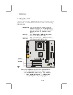
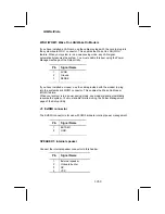
WOL1/WOM1: Wake On LAN/Wake On Modem  


If you have installed a LAN card, use the cable provided with the card to plug into 
the system board WOL1 connector. This enables the Wake On LAN (WOL) 
feature. When your system is in a power-saving mode, any LAN signal 
automatically resumes the system. You must enable this item using the Power 
Management page of the Setup Utility. 


Pin Signal 

Name 


5VSB 
Ground 
SENSE 


If you have installed a modem, use the cable provided with the modem to plug 
into the system board WOM1 connector. This enables the Wake On Modem 
(WOM) feature.  
When your system is in a power-saving mode, any modem signal automatically 
resumes the system. You must enable this item using the Power Management 
page of the Setup Utility.  
 

J1: ExtSMI connector 


The ExtSMI connector is for use with SMI hardware interrupt power management.  


Pin Signal 

Name 


EXTSMI 
GND 


SPEAKER1: Internal speaker 


Connect the internal speaker connector to this header. 
 

Pin Signal 

Name 


External speaker  
Onboard buzzer 
NC 
VCC 


29/

53 

Summary of Contents for NetVista 6049

Page 1: ...cal information about IBM products should be made to your IBM Authorized Dealer your IBM Marketing Representative or your IBM Retailer Address comments about this publication to the IBM HelpCenter Cop...

Page 2: ...al Connector Color Coding 13 Connects Power cords 13 Basic trouble shooting 14 System Summary NetVista Type 6049 16 System Summary NetVista Type 2259 17 Hardware Descriptions 18 System Board Descripti...

Page 3: ...tus Option 45 Load Defaults Option 45 Set Supervisor and User Passwords Options 46 Save Exit Setup Option 46 Exit Without Saving 46 IBM Statement of Limited Warranty 48 Part 1 General Terms 48 The IBM...

Page 4: ...can send license inquiries in writing to the IBM Director of Licensing IBM Corporation North Castle Drive Armonk NY 10504 1785 U S A IBM makes no representations whatsoever about any non IBM Web site...

Page 5: ...e installation and configuration procedures Connect and disconnect cables as described in the following table when installing moving or opening covers on this product or attached devices To connect To...

Page 6: ...ves and DVD ROM drives are laser products These drives are certified in the U S to conform to the requirements of the Department of Health and Human Services 21 Code of Federal Regulations DHHS 21 CFR...

Page 7: ...good support The seat should have a curved front to relieve pressure on the thighs Adjust the seat so that your thighs are parallel to the floor and your feet are either flat on the floor or on a foo...

Page 8: ...ods of reducing glare Dust buildup compounds problems associated with glare Remember to clean your monitor screen periodically using a soft cloth moistened with a nonabrasive liquid glass cleaner Air...

Page 9: ...static electricity to build up around you Always handle components carefully Handle adapters and memory modules by the edges Never touch any exposed circuitry Prevent others from touching components...

Page 10: ...n for the first time your computer automatically selected settings for monitor performance Depending on the monitor you have you might want to change some of these settings for optimal performance Usi...

Page 11: ...t Button Diskette Drive Diskette Drive Light Power On Light Storage Bay Knob Power On Switch Voltage Selection Switch Power Connector USB two Ethernet SVGA Monitor Serial 1 Serial 2 Parallel Audio jac...

Page 12: ...a PS 2 keyboard LAN Port If your system board comes with the LAN option you can connect an RJ 45 cable to the LAN port USB Ports Use the USB ports to connect USB devices LPT1 Use LPT1 to connect prin...

Page 13: ...selector switch should be preset for your area however contact your local power company if you are uncertain of the voltage for your area If the voltage supply range in your area is 100 127V set the...

Page 14: ...to ensure that the power is on If you cannot correct the problem have the computer serviced The monitor screen is blank Verify that The monitor cable is securely attached to the rear of the monitor an...

Page 15: ...urely connected to the mouse connector on the computer If you cannot correct the problem have the computer serviced The operating system will not start Verify that There is no diskette in the diskette...

Page 16: ...D x 1 with 20 60GB capacity and ATA 100 interface 5 25 inch x 1 with CD ROM 48x One open bay 5 25 inch for optional optical devices Audio Subsystem AC97 Audio Codec System Beeper only Network Interfac...

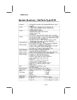
Page 17: ...5 inch x 1 with DVD CD RW or CD ROM 48x One open bay 5 25 inch for optional optical devices Audio Subsystem AC97 Audio Codec External speaker Bricks Network Interface RealTek 8100 Ethernet 100 10base...

Page 18: ...VID1 VID2 VID3 VID4 1 1 1 1 1 1 1 1 1 1 1 1 1 1 LED1 AGP1 PCI1 PCI2 PCI3 CNR1 BAT1 WOL1 WOM1 SPEAKER1 IDE1 IDE2 DIMM1 DIMM2 DIMM3 CPU SOCKET CPUFAN1 CASFAN1 ATX1 ATX3 CDIN1 CDIN2 JP1 LED1 J2 J1 IR1 F...

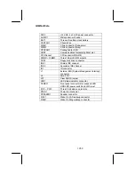
Page 19: ...M3 Three 168 pin DIMM sockets FDD1 Floppy disk drive connector IDE 1 Primary IDE channel IDE 2 Secondary IDE channel IR1 IR connector J1 External SMI System Management Interrupt connector J2 Smart I O...

Page 20: ...IBM NetVista The illustration below shows the location of System Board Power supply I O devices and option slots in a tower type case Power Supply Unit Drive Cage Expansion Slots I O Template 20 53...

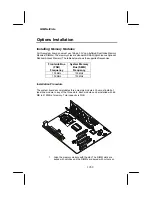
Page 21: ...supported frequencies Frontside Bus FSB Frequency System Memory Bus SMB Frequency 100 MHz 100 MHz 100 MHz 133 MHz Installation Procedure The system board accommodates three memory modules You must in...

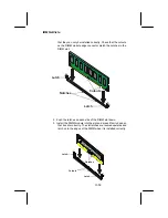
Page 22: ...in the DIMM slot Cutouts Notches Latch Latch 2 Push the latches on each side of the DIMM slot down 3 Install the DIMM module into the slot and press it firmly down so that it seats correctly The slot...

Page 23: ...el IDE devices have jumpers or switches that are used to set the IDE device as MASTER or SLAVE When installing two IDE devices on one cable ensure that one device is set to MASTER and the other device...

Page 24: ...cable connector into the hard disk drive IDE connector B It doesn t matter which connector on the cable you use 4 Plug a power cable from the case power supply into the power connector on the hard di...

Page 25: ...bbon cable is always marked with a colored stripe on the cable 3 Plug an IDE cable connector into the CD ROM DVD drive IDE connector B It doesn t matter which connector on the cable you use 4 Plug a p...

Page 26: ...e the 32 bit PCI interface CNR Slot This slot is used to insert CNR cards including LAN Modem and Audio functions CPUFAN1 PFAN1 CASFAN1 DIMM1 DIMM3 DIMM2 IDE2 ATX1 ATX2 ATX3 CDIN1 AGP1 PCI1 PCI2 PCI3...

Page 27: ...is correctly seated in the slot Edge connector Edge connector Add on card 3 Secure the metal bracket of the card to the system chassis with a screw Note For some add on cards for example graphics adap...

Page 28: ...OM1 PANEL1 SPEAKER1 J1 J2 FDD1 CDIN2 AUDIO1 IDE1 VID0 VID1 VID2 VID3 VID4 1 1 1 1 1 1 1 1 1 1 1 1 LED1 AUDIO1 WOL1 USB2 IR1 WOM1 J2 SPEAKER1 J1 1 1 1 1 1 AUDIO1 Front panel audio header This system bo...

Page 29: ...ENSE If you have installed a modem use the cable provided with the modem to plug into the system board WOM1 connector This enables the Wake On Modem WOM feature When your system is in a power saving m...

Page 30: ...16 17 18 19 20 VCC3 VCC3 GND GND 5VSB GND GND RESERVED GND VCC5 VCC5 Replacing the system battery Follow these steps to replace the battery 1 Place the blade of a small flat blade screwdriver under t...

Page 31: ...how the computer performs Before using the Setup Utility ensure that you understand the Setup Utility options This chapter provides explanations for Setup Utility options The Standard Configuration A...

Page 32: ...on a menu PU PD Modifies the selected field s values F10 Saves the current configuration and exits setup F1 Displays a screen that describes all key functions F5 Loads previously saved values to CMOS...

Page 33: ...l Press Enter to enter next page for detail hard drive settings Move Enter Select PU PD Value F10 Save ESC Exit F1 General Help F5 Previous Values F7 Default Settings Processor This item displays info...

Page 34: ...e configuration information supplied by the manufacturer of your hard drive Incorrect settings can result in your system not recognizing the installed hard disk Access Mode Auto This item defines ways...

Page 35: ...ral Help F5 Previous Values F7 Default Settings Anti Virus Protection Disabled When enabled this item provides protection against viruses that try to write to the boot sector and partition table of yo...

Page 36: ...delay settings for your keyboard Typematic Rate Chars Sec Use this item to define how many characters per second are generated by a held down key Typematic Delay Msec Use this item to define how many...

Page 37: ...lay information about the system board computer and system BIOS These fields are display only CMOS Setup Utility Copyright C 1984 2001 Award Software Product Data Item Help Machine Type IBM System Boa...

Page 38: ...vious Values F7 Default Settings On Chip Primary Secondary PCI IDE Enabled Use these items to enable or disable the PCI IDE channels that are integrated on the system board IDE Primary Secondary Maste...

Page 39: ...d if your IDE hard drive supports block mode Block mode enables BIOS to automatically detect the optimal number of block read and writes per sector that the drive can support and improves the speed of...

Page 40: ...ower saving mode If any item in the list of Reload Global Timer Events is Enabled then any activity on that item will reset the timeout counters to zero If the system is suspended or has been powered...

Page 41: ...short timeout If this item is set to Min Saving power saving modes occur after a longer timeout If the item is set to User Define you can insert your own timeouts for the power saving modes Video Off...

Page 42: ...ke Up On LAN Enabled When set to Enabled the system power will be turned on if the LAN port receives an incoming signal You have to connect the fax modem to the system board Wake On LAN connector for...

Page 43: ...Q For USB Enabled INT Pin 1 Assignment Auto INT Pin 2 Assignment Auto INT Pin 3 Assignment Auto INT Pin 4 Assignment Auto INT Pin 5 Assignment Auto INT Pin 6 Assignment Auto INT Pin 7 Assignment Auto...

Page 44: ...te snooping so you must leave this item disabled Assign IRQ For USB Enabled Names the interrupt request IRQ line assigned to the USB on your system Activity of the selected IRQ always awakens the syst...

Page 45: ...ch before powering down System Component Characteristics These fields provide you with information about the systems current operating status You cannot make changes to these fields CPU Vcore CPU core...

Page 46: ...f you are deleting a password that is already installed press Enter when the password dialog box appears You see a message that indicates that the password has been disabled PASSWORD DISABLED Press an...

Page 47: ...IBM NetVista Note If you have made settings that you do not want to save use the Exit Without Saving item and press Y to discard any changes you have made 47 53...

Page 48: ...Specifications The warranty period for a Machine is a specified fixed period commencing on its Date of Installation The date on your sales receipt is the Date of Installation unless IBM or your resell...

Page 49: ...ther at your location or a service center IBM or your reseller will also manage and install selected engineering changes that apply to the Machine Some parts of IBM Machines are designated as Customer...

Page 50: ...er liability you are entitled to recover damages from IBM In each such instance regardless of the basis on which you are entitled to claim damages from IBM including fundamental breach negligence misr...

Page 51: ...dinarily acquired for personal domestic or household use or consumption then none of the limitations in this paragraph apply Governing Law The following replaces laws of the country in which you acqui...

Page 52: ...ms 1 and 2 of this Section 1 liability for bodily injury including death or damage to real property and tangible personal property will be limited to that caused by IBM s negligence 2 as to any other...

Page 53: ...Agreement will first be resolved by friendly negotiations failing which either of us has the right to submit the dispute to the China International Economic and Trade Arbitration Commission in Beijin...

Reviews: