


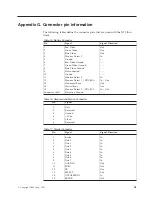


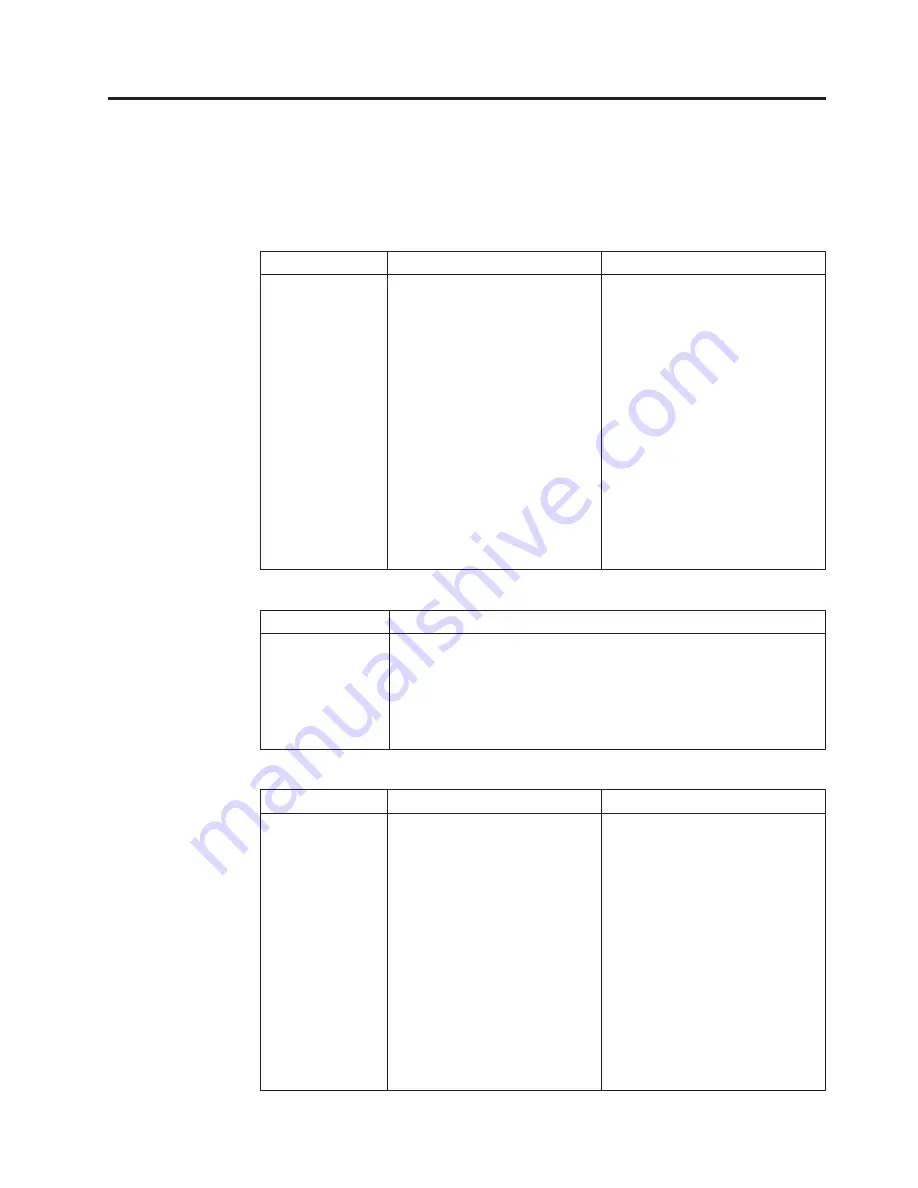
Appendix G. Connector pin information
The following tables define the connector pins that are used with the N70 thin
client.
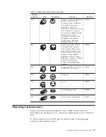
Table 15. Monitor Connector
Pin
Signal
Signal Direction
1
Red Video
Out
2
Green Video
Out
3
Blue Video
Out
4
Monitor Detect 2
In
5
Ground
– - -
6
Red Video Ground
- - -
7
Green Video Ground
- - -
8
Blue Video Ground
- - -
9
Not connected
- - -
10
Ground
- - -
11
Monitor Detect 0
In
12
Monitor Detect 1 / DDCSDA
In / Out
13
Horizontal Sync
Out
14
Vertical Sync
Out
15
Monitor Detect 3 / DDCSCL
In / Out
Connector shell
Protective Ground
- - -
Table 16. Keyboard and Mouse Connectors
Pin
Signal
1
Data
2
Reserved
3
Ground
4
+5V dc
5
Clock
6
Reserved
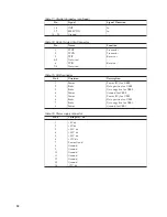
Table 17. Parallel Connector
Pin
Signal
Signal Direction
1
Strobe
In
2
Data 0
In
3
Data 1
In
4
Data 2
In
5
Data 3
In
6
Data 4
In
7
Data 5
In
8
Data 6
In
9
Data 7
In
10
ACKNLG
Out
11
BUSY
Out
12
PE
Out
13
SELECT
Out
14
AUTOFEEDXT
In
15
ERROR
Out
© Copyright IBM Corp. 2001
51


