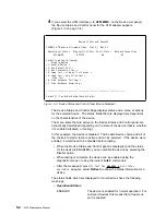
ESCON-only Tests
Run the Light Test on the New Fiber Optic Cable
After you have run diagnostics on the new ESCON adapter and verified that it is
functioning correctly, you can test that the fiber optic cable is connected correctly
and transmitting light to the adapter.
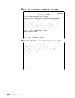
1
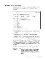
From the Device Status and Controls Menu, select Run Interactive Test to
display the Test Options panel.
@
Screen 1 of 1
Test Options
LIC 287 - ESCON Channel Adapter, Slot 4
Operational Status
Diagnostic Status
Fault Status
Network Connection
NOT CONFIGURED
MESSAGE
OK
UNKNOWN
Do not remove this device while testing.
Select one of the following test options:
* < 1. Run all tests excluding external wrap test >
* < 2. Run all tests including external wrap test >
Individual tests:
* < 3. PCI BUS >
* < 4. PROCESSOR >
* < 5. MEMORY >
* < 6. MEMORY PROT >
* < 7. TIMER >
* < 8. AIB >
* < 9. WRAP PLUG >
* <10. OPTICAL POWER >
* <11. LIGHT RECEPTION >
Select (1-11 or
B=Back R=Refresh H=Help ):11
2
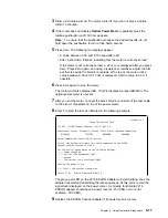
Enter 11 on the Test Options Panel to run the light reception test. At this
point, the following panel appears.
@
Screen 1 of 1
Setup For Light Reception Test
LIC 287 - ESCON Channel Adapter, Slot 4, Net # 0
Operational Status
Diagnostic Status
Fault Status
Network Connection
NOT CONFIGURED
TESTING
OK
UNKNOWN
First, be sure that you have successfully run the Wrap Plug Test on slot 4.
Then, remove the wrap plug from the ESCON adapter
(if still installed).
Connect the fiber for an operational ESCON channel to the adapter located in
slot 4.
Confirm that the correct fiber is installed.
< 1. Start test. >
Select (1 or
B=Back R=Refresh H=Help ):1
5-12
2216 Maintenance Manual
Summary of Contents for Nways 2216
Page 1: ...2216 Nways Multiaccess Connector ÉÂÔ Service and Maintenance Manual SY27 0350 02 ...
Page 2: ......
Page 3: ...2216 Nways Multiaccess Connector ÉÂÔ Service and Maintenance Manual SY27 0350 02 ...
Page 8: ...vi 2216 Maintenance Manual ...
Page 10: ...Common Tasks and the IBM 2216 Library viii 2216 Maintenance Manual ...
Page 45: ...6 Remove the adapter from its location Chapter 2 Removal and Replacement Procedures 2 15 ...
Page 60: ...3 6 2216 Maintenance Manual ...
Page 84: ...4 24 2216 Maintenance Manual ...
Page 104: ...A 2 2216 Maintenance Manual ...
Page 106: ...Assembly 1 Final Assembly 2216 Model 400 B 2 2216 Maintenance Manual ...
Page 110: ...B 6 2216 Maintenance Manual ...
Page 114: ...1 2 3 4 5 6 7 8 9 10 Figure C 1 Power Cord Plugs by Country C 4 2216 Maintenance Manual ...
Page 138: ...F 12 2216 Maintenance Manual ...
Page 164: ......
Page 167: ......


