background image

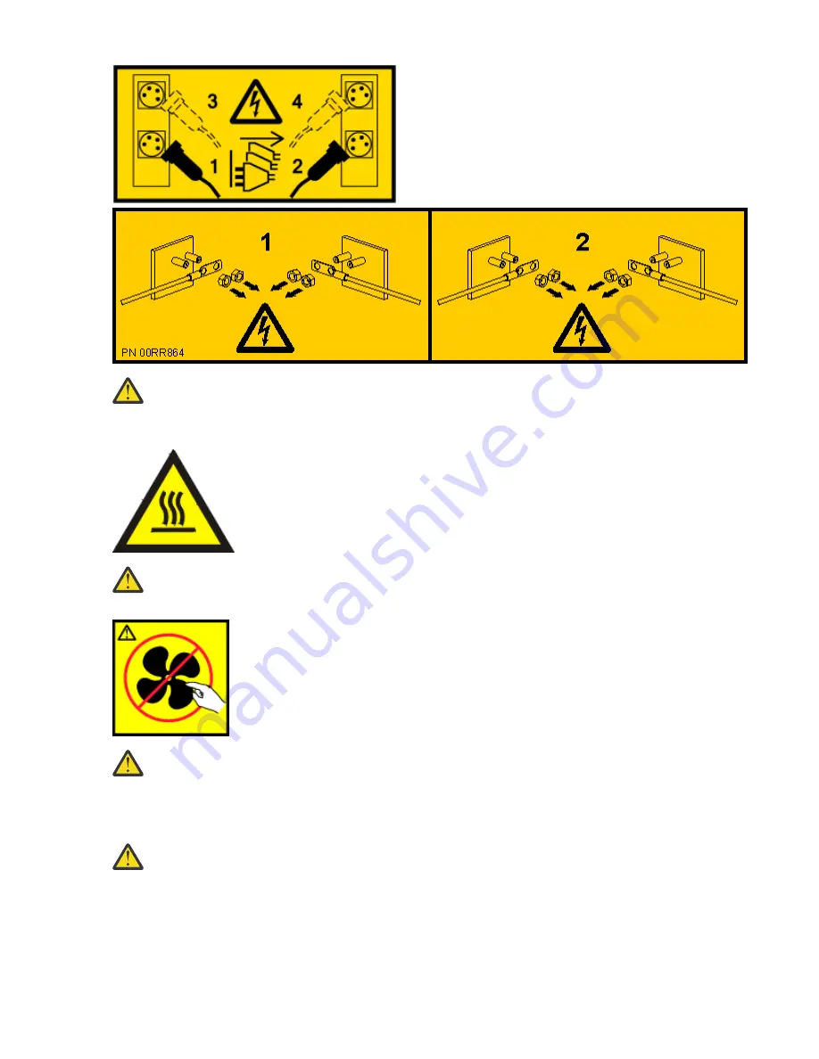
DANGER: Multiple power cords. The product might be equipped with multiple AC power cords or

multiple DC power cables. To remove all hazardous voltages, disconnect all power cords and

power cables. (L003)

(L007)

CAUTION: A hot surface nearby. (L007)

(L008)

CAUTION: Hazardous moving parts nearby. (L008)

All lasers are certified in the U.S. to conform to the requirements of DHHS 21 CFR Subchapter J for class 1

laser products. Outside the U.S., they are certified to be in compliance with IEC 60825 as a class 1 laser

product. Consult the label on each part for laser certification numbers and approval information.

CAUTION: This product might contain one or more of the following devices: CD-ROM drive, DVD-

ROM drive, DVD-RAM drive, or laser module, which are Class 1 laser products. Note the following

information:
• Do not remove the covers. Removing the covers of the laser product could result in exposure to

hazardous laser radiation. There are no serviceable parts inside the device.

• Use of the controls or adjustments or performance of procedures other than those specified

herein might result in hazardous radiation exposure.

(C026)

x  Power Systems: Installing and Servicing the OpenCAPI adapter support for the 8335-GTH system

Summary of Contents for OpenCAPI

Page 1: ...Power Systems Installing and Servicing the OpenCAPI adapter support for the 8335 GTH system IBM ...

Page 2: ...l G229 9054 and the IBM Environmental Notices and User Guide Z125 5823 This edition applies to IBM Power Systems servers that contain the POWER9 processor and to all associated models Copyright International Business Machines Corporation 2019 2020 US Government Users Restricted Rights Use duplication or disclosure restricted by GSA ADP Schedule Contract with IBM Corp ...

Page 3: ...35 GTC 8335 GTG 8335 GTH 8335 GTW or 8335 GTX system 39 Sensor status 39 Removing and replacing covers 40 Removing the service access cover 40 Installing the service access cover 41 Removing the front cover 42 Installing the front cover 43 Service and operating positions 43 Placing the system into the service position 43 Placing the system into the operating position 45 Removing and replacing powe...

Page 4: ...iv ...

Page 5: ...ordnung geeignet Laser safety information IBM servers can use I O cards or features that are fiber optic based and that utilize lasers or LEDs Laser compliance IBM servers may be installed inside or outside of an IT equipment rack DANGER When working on or around the system observe the following precautions Electrical voltage and current from power telephone and communication cables are hazardous ...

Page 6: ...ower cords to the outlets 5 For racks with a DC power distribution panel PDP restore the power from the Customer s DC power source and turn on the circuit breakers located in the PDP 6 Turn on the devices Sharp edges corners and joints may be present in and around the system Use care when handling equipment to avoid cuts scrapes and pinching D005 R001 part 1 of 2 DANGER Observe the following preca...

Page 7: ...ompromise the supply wiring or overcurrent protection To provide the correct power connection to a rack refer to the rating labels located on the equipment in the rack to determine the total power requirement of the supply circuit For sliding drawers Do not pull out or install any drawer or feature if the rack stabilizer brackets are not attached to the rack or if the rack is not bolted to the flo...

Page 8: ...llowing steps Lower the four leveling pads Install stabilizer brackets on the rack cabinet or in an earthquake environment bolt the rack to the floor If you removed any devices from the rack cabinet repopulate the rack cabinet from the lowest position to the highest position If a long distance relocation is required restore the rack cabinet to the configuration of the rack cabinet as you received ...

Page 9: ... not put any load on the slide rail mounted equipment mounted in the installation position Do not leave the slide rail mounted equipment in the installation position L002 L003 or or or or Safety notices ix ...

Page 10: ...roduct Consult the label on each part for laser certification numbers and approval information CAUTION This product might contain one or more of the following devices CD ROM drive DVD ROM drive DVD RAM drive or laser module which are Class 1 laser products Note the following information Do not remove the covers Removing the covers of the laser product could result in exposure to hazardous laser ra...

Page 11: ...ed for use to assist lift install remove units load up into rack elevations It is not to be used loaded transporting over major ramps nor as a replacement for such designated tools like pallet jacks walkies fork trucks and such related relocation practices When this is not practicable specially trained persons or services must be used for instance riggers or movers Read and completely understand t...

Page 12: ...ccident could cause serious injury Not for moving humans Make certain clicking sound is heard as the equipment is being raised Be sure winch is locked in position before releasing handle Read instruction page before operating this winch Never allow winch to unwind freely Freewheeling will cause uneven cable wrapping around winch drum damage cable and may cause serious injury This TOOL must be main...

Page 13: ...ed DC return DC I design The DC battery return terminal shall not be connected to the chassis or frame ground The dc powered system is intended to be installed in a common bonding network CBN as described in GR 1089 CORE Safety notices xiii ...

Page 14: ...xiv Power Systems Installing and Servicing the OpenCAPI adapter support for the 8335 GTH system ...

Page 15: ...he interposer card must be installed in the GPU 3 location on the system backplane replacing a GPU in that position A GPU in position 4 must be removed and replaced with an air baffle The system supports two GPUs in GPU positions 1 and 2 when the interposer card is installed An OpenCAPI cable connects between the interposer and the OpenCAPI PCIe adapter If you need to replace the interposer card o...

Page 16: ...2 Power Systems Installing and Servicing the OpenCAPI adapter support for the 8335 GTH system ...

Page 17: ...rear ESD jack or to an unpainted metal surface of your hardware to prevent the electrostatic discharge from damaging your hardware When you use an ESD wrist strap follow all electrical safety procedures An ESD wrist strap is used for static control It does not increase or decrease your risk of receiving electric shock when using or working on electrical equipment If you do not have an ESD wrist st...

Page 18: ...rews that are shown in the following figure b Grasp the GPU by the heat sink being careful not to bend the pins Remove the GPU from the system backplane Be careful of the pins on the bottom of the GPUs to avoid damaging the pins and the GPU c Place the protective covers on the bottom of the removed GPUs 4 Power Systems Installing and Servicing the OpenCAPI adapter support for the 8335 GTH system ...

Page 19: ...Thread the four inner screws half way using the sequence that is shown After all four screws are threaded then fully tighten them Next tighten the outer four screws 0 47 in 12 mm in length by using the sequence that is shown Take care to not damage the system backplane with the screw driver tip Installing the OpenCAPI adapter support on the 8335 GTH system 5 ...

Page 20: ...abel and remove any plugs that extend out of the rear OpenCAPI PCIe adapter 7 Attach the OpenCAPI cable to the OpenCAPI PCIe adapter as shown in the following figure 6 Power Systems Installing and Servicing the OpenCAPI adapter support for the 8335 GTH system ...

Page 21: ...igure 5 Inserting the OpenCAPI cable into the PCIe adapter 8 Pass the OpenCAPI cable through the bulkhead as shown in the following figure Installing the OpenCAPI adapter support on the 8335 GTH system 7 ...

Page 22: ...ert the OpenCAPI PCIe adapter into PCIe adapter slot 4 Align the adapter properly and insert it fully into the slot as shown in the following figure 8 Power Systems Installing and Servicing the OpenCAPI adapter support for the 8335 GTH system ...

Page 23: ...7 Inserting the PCIe adapter 10 Attach the OpenCAPI cable to the OpenCAPI interposer adapter in GPU position 3 as shown in the following figure Installing the OpenCAPI adapter support on the 8335 GTH system 9 ...

Page 24: ...plugs that you removed from the rear of the OpenCAPI PCIe adapter 12 Install the air baffle A onto the interposer Use four screws 0 16 in 4 mm in length at B secure the air baffle to the interposer 10 Power Systems Installing and Servicing the OpenCAPI adapter support for the 8335 GTH system ...

Page 25: ...ser air baffle 13 Install a GPU air baffle A into GPU position 4 Use four screws 0 16 in 4 mm in length in positions B to secure the air baffle to the system backplane Installing the OpenCAPI adapter support on the 8335 GTH system 11 ...

Page 26: ...system for operation For instructions see Preparing the 8335 GTC 8335 GTG 8335 GTH 8335 GTW or 8335 GTX system for operation after you remove and replace internal parts on page 36 12 Power Systems Installing and Servicing the OpenCAPI adapter support for the 8335 GTH system ...

Page 27: ...discharge ESD wrist strap to the front ESD jack to the rear ESD jack or to an unpainted metal surface of your hardware to prevent the electrostatic discharge from damaging your hardware When you use an ESD wrist strap follow all electrical safety procedures An ESD wrist strap is used for static control It does not increase or decrease your risk of receiving electric shock when using or working on ...

Page 28: ...y plugs that extend out of the rear OpenCAPI PCIe adapter 4 Remove the OpenCAPI PCIe adapter from PCIe adapter slot 4 as shown in the following figure Carefully pass the cable through the bulkhead 14 Power Systems Installing and Servicing the OpenCAPI adapter support for the 8335 GTH system ...

Page 29: ...Figure 12 Removing a PCIe adapter 5 Remove the OpenCAPI cable from the OpenCAPI PCIe adapter as shown in the following figure Removing and replacing OpenCAPI adapter support on the 8335 GTH system 15 ...

Page 30: ...oving the OpenCAPI cable from the PCIe adapter 6 Remove the air baffle A from the interposer Remove the four screws at B 16 Power Systems Installing and Servicing the OpenCAPI adapter support for the 8335 GTH system ...

Page 31: ...air baffle 7 Remove the eight screws and remove the old interposer from GPU position 3 as shown in the following figure Do not unscrew the four inner most screws Removing and replacing OpenCAPI adapter support on the 8335 GTH system 17 ...

Page 32: ...d the four inner screws half way using the sequence that is shown After all four screws are threaded then fully tighten them Next tighten the outer four screws 0 47 in 12 mm in length by using the sequence that is shown Take care to not damage the system backplane with the screw driver tip 18 Power Systems Installing and Servicing the OpenCAPI adapter support for the 8335 GTH system ...

Page 33: ...ure 16 Installing the OpenCAPI interposer 9 Attach the OpenCAPI cable to the OpenCAPI PCIe adapter as shown in the following figure Removing and replacing OpenCAPI adapter support on the 8335 GTH system 19 ...

Page 34: ...ng the OpenCAPI cable into the PCIe adapter 10 Pass the OpenCAPI cable through the bulkhead as shown in the following figure 20 Power Systems Installing and Servicing the OpenCAPI adapter support for the 8335 GTH system ...

Page 35: ...able 11 Insert the OpenCAPI PCIe adapter into PCIe adapter slot 4 Align the adapter properly and insert it fully into the slot as shown in the following figure Removing and replacing OpenCAPI adapter support on the 8335 GTH system 21 ...

Page 36: ...e PCIe adapter 12 Attach the OpenCAPI cable to the OpenCAPI interposer adapter in GPU position 3 as shown in the following figure 22 Power Systems Installing and Servicing the OpenCAPI adapter support for the 8335 GTH system ...

Page 37: ...eplace any plugs that you removed from the rear of the OpenCAPI PCIe adapter 14 Install the air baffle A onto the interposer Use four screws 0 16 in 4 mm in length at B secure the air baffle to the interposer Removing and replacing OpenCAPI adapter support on the 8335 GTH system 23 ...

Page 38: ... system for operation For instructions see Preparing the 8335 GTC 8335 GTG 8335 GTH 8335 GTW or 8335 GTX system for operation after you remove and replace internal parts on page 36 24 Power Systems Installing and Servicing the OpenCAPI adapter support for the 8335 GTH system ...

Page 39: ...that the outlet supplies proper voltage and phase rotation according to the system rating plate For racks with a DC power distribution panel PDP connect the customer s DC power source to the PDP Ensure that the proper polarity is used when attaching the DC power and DC power return wiring Connect any equipment that will be attached to this product to properly wired outlets When possible use one ha...

Page 40: ...k to the installation position read the installation instructions Do not put any load on the slide rail mounted equipment mounted in the installation position Do not leave the slide rail mounted equipment in the installation position Each rack cabinet might have more than one power cord For AC powered racks be sure to disconnect all power cords in the rack cabinet when directed to disconnect power...

Page 41: ...ck stabilizer brackets are not attached to the rack or if the rack is not bolted to the floor Do not pull out more than one drawer at a time The rack might become unstable if you pull out more than one drawer at a time For fixed drawers This drawer is a fixed drawer and must not be moved for servicing unless specified by the manufacturer Attempting to move the drawer partially or completely out of...

Page 42: ...hazardous voltages disconnect all power cords and power cables L003 L005 CAUTION Hazardous energy present Voltages with hazardous energy might cause heating when shorted with metal which might result in splattered metal burns or both L005 28 Power Systems Installing and Servicing the OpenCAPI adapter support for the 8335 GTH system ...

Page 43: ...e contacts http www ibm com planetwide 7 If you encounter difficulties during the installation contact your service provider your IBM reseller or your next level of support 8 For the IBM Power System AC922 8335 GTC 8335 GTG and 8335 GTH or IBM Power System AC922 8335 GTW and 8335 GTX systems ensure that the top cover is on when the system is running for thermal performance Identifying the system t...

Page 44: ...Figure 22 Front LEDs with bezel on Figure 23 Front LEDs with bezel off 30 Power Systems Installing and Servicing the OpenCAPI adapter support for the 8335 GTH system ...

Page 45: ...at needs servicing Learn how to turn on the blue identify LED to help you find the system that needs servicing Procedure To activate the blue system identify LED use the following command openbmctool U username P password H BMC IP address or BMC host name chassis identify on To turn off the blue system identify LED use the following command openbmctool U username P password H BMC IP address or BMC...

Page 46: ...It does not increase or decrease your risk of receiving electric shock when using or working on electrical equipment If you do not have an ESD wrist strap just prior to removing the product from ESD packaging and installing or replacing hardware touch an unpainted metal surface of the system for a minimum of 5 seconds If at any point in this service process you move away from the system it is impo...

Page 47: ...or or or or Common procedures for servicing or installing features in the 8335 GTC 8335 GTG 8335 GTH 8335 GTW or 8335 GTX system 33 ...

Page 48: ...05 9 Remove the power supplies from the system as shown in Figure 25 on page 35 a To release a power supply from its position in the system pull the locking tab A to the left b Grasp the power supply handle with one hand and pull the power supply B partially out of the system c Place your other hand underneath the power supply and pull the power supply out of the system and place it on an ESD mat ...

Page 49: ... not place any object on top of a rack mounted device unless that rack mounted device is intended for use as a shelf R008 L012 CAUTION Pinch hazard L012 11 Remove the service access cover For instructions see Removing the service access cover from an 8335 GTC 8335 GTG 8335 GTH 8335 GTW or 8335 GTX system on page 40 Common procedures for servicing or installing features in the 8335 GTC 8335 GTG 833...

Page 50: ...over on an 8335 GTC 8335 GTG 8335 GTH 8335 GTW or 8335 GTX system on page 41 3 Place the system into the operating position For instructions see Placing an 8335 GTC 8335 GTG 8335 GTH 8335 GTW or 8335 GTX system into the operating position on page 45 L012 CAUTION Pinch hazard L012 Attention For a water cooled system before you power on the system ensure that cooling water is circulating through the...

Page 51: ...tructions see Configuring the BMC IP address www ibm com support knowledgecenter POWER9 p9eih p9eih_configuring_bmc_ip htm 10 Enter the network settings that you recorded earlier For instructions see Network settings www ibm com support knowledgecenter POWER9 p9eih p9eih_openbmc_networksetting htm 11 Replace the front cover For instructions see Installing the front cover on an 8335 GTC 8335 GTG 83...

Page 52: ...circulating through the system You can use this procedure to power on the system or you can use a console to power on the system Procedure 1 Open the front rack door if necessary 2 Before you press the power button ensure that the power supplies are connected to the system unit and verify the following items All system power cables are connected to a power source The power on LED as shown in Figur...

Page 53: ...the system to shut down and then power off The indicates the time in minutes before the shutdown occurs Sensor status You can check the sensor status to quickly determine the general health of the system without using the event codes To view the sensor status use the following command openbmctool U username P password H BMC IP address or BMC host name fru status To view the sensor status and any c...

Page 54: ...ce access cover from an 8335 GTC 8335 GTG 8335 GTH 8335 GTW or 8335 GTX system To remove the service access cover complete the steps in this procedure Procedure 1 Ensure that you removed both power supplies from the system For instructions see Preparing the 8335 GTC 8335 GTG 8335 GTH 8335 GTW or 8335 GTX system to remove and replace internal parts on page 32 L005 CAUTION Hazardous energy present V...

Page 55: ...X system To replace the service access cover complete the steps in this procedure About this task Attention For safety airflow purposes and thermal performance the service access cover must be installed and fully seated before powering on the system on Procedure 1 Place the cover A on the system unit such that the alignment pins on the cover are aligned to the slots on the chassis Slide the cover ...

Page 56: ...ary open the front rack door 2 Ensure that you have the electrostatic discharge ESD wrist strap on and that the ESD clip is plugged into a ground jack or connected to an unpainted metal surface If not do so now 3 If applicable remove the screws that are on both sides of the cover to disengage the cover from the system unit 4 Pull the cover away from the system 42 Power Systems Installing and Servi...

Page 57: ...ating position Placing an 8335 GTC 8335 GTG 8335 GTH 8335 GTW or 8335 GTX system into the service position To place a system into the service position complete the steps in this procedure About this task Pick the proper type of rails for your system Slide rails on page 43 Fixed rails on page 44 Slide rails Use this procedure when your system is installed using slide rails Before you begin Notes Wh...

Page 58: ... the rack Note When you place the system into the service position you must ensure that all stability plates are firmly installed to prevent the rack from toppling Ensure that only one system unit is removed at a time Procedure 1 Label and disconnect the cables at the rear of the system unit 2 For a water cooled system label and disconnect the water hoses at the manifold Pull the coupling toward y...

Page 59: ... person on the right side of the system 6 Tilt and lift the system from the rails 7 Carefully set the system on a table with an appropriate ESD surface Placing an 8335 GTC 8335 GTG 8335 GTH 8335 GTW or 8335 GTX system into the operating position To place a system into the operating position complete the steps in this procedure About this task Pick the proper type of rails for your system Slide rai...

Page 60: ... Procedure 1 Unlock the blue rail safety latches A by lifting them upward 2 Align the system unit on to the rails and push the system unit back into the rack until both release latches lock into position See Figure 33 on page 46 Figure 33 Placing the system into the operating position 3 Replace the screws on either side of the system that secure the system to the rack 46 Power Systems Installing a...

Page 61: ... the system into position over the fixed rack rails 4 Carefully lower the system until the rear of the system rests on the rails 5 While one person is supporting the weight of the system have the second person move to the front of the system and push the system all the way into the rack 6 Using your labels reconnect the cables at the rear of the system unit 7 For a water cooled system connect the ...

Page 62: ... and 8335 GTH or IBM Power System AC922 8335 GTW and 8335 GTX system Disconnecting power cords from an 8335 GTC 8335 GTG 8335 GTH 8335 GTW or 8335 GTX system To disconnect a power cord complete the steps in this procedure Procedure 1 Open the rear rack door on the system unit that you are servicing 2 Identify the system unit that you are servicing in the rack 3 Label and disconnect the power cords...

Page 63: ...need to make that same loop when you reattach the power cords Figure 35 on page 49 and Figure 36 on page 50 shows how to loop the cables Figure 35 Routing the power cord loop in the cable management arm Common procedures for servicing or installing features in the 8335 GTC 8335 GTG 8335 GTH 8335 GTW or 8335 GTX system 49 ...

Page 64: ...e 37 on page 51 Note This system might be equipped with two or more power supplies If the removing and replacing procedures require the power to be off then ensure that all the power sources to the system are disconnected 50 Power Systems Installing and Servicing the OpenCAPI adapter support for the 8335 GTH system ...

Page 65: ...dure 1 Open the rear rack door on the system unit that you are servicing 2 Using your labels reconnect the power cords to the system unit as shown in Figure 38 on page 51 Figure 38 Connecting the power cords to the system 3 Loop and attach the power cords to the power supply handle Common procedures for servicing or installing features in the 8335 GTC 8335 GTG 8335 GTH 8335 GTW or 8335 GTX system ...

Page 66: ...d loop fastener to tie the power cord to the power supply handle Figure 39 on page 52 and Figure 40 on page 53 shows how to loop the cables Figure 39 Routing the power cord loop in the cable management arm 52 Power Systems Installing and Servicing the OpenCAPI adapter support for the 8335 GTH system ...

Page 67: ...cedure 1 Are you able to connect the BMC card to the network with a Dynamic Host Configuration Protocol DHCP IP address If Then Yes Update the system firmware level of the BMC card to OP940 20 or later For instructions see Updating the system firmware by using the OpenBMC tool If you are not able to update the system firmware level continue with the next step No Continue with the next step Common ...

Page 68: ...ESD wrist strap follow all electrical safety procedures An ESD wrist strap is used for static control It does not increase or decrease your risk of receiving electric shock when using or working on electrical equipment If you do not have an ESD wrist strap just prior to removing the product from ESD packaging and installing or replacing hardware touch an unpainted metal surface of the system for a...

Page 69: ... place it in the service position For instructions see Preparing the 8335 GTC 8335 GTG 8335 GTH 8335 GTW or 8335 GTX system to remove and replace internal parts on page 32 10 Attach the electrostatic discharge ESD wrist strap The ESD wrist strap must be connected to an unpainted metal surface until the service procedure is completed and if applicable until the service access cover is replaced Atte...

Page 70: ...process you move away from the system it is important to again discharge yourself by touching an unpainted metal surface for at least 5 seconds before you continue with the service process 11 Remove the air baffles 12 Remove the system processor jumpers from the system backplane as shown in Figure 42 on page 56 Figure 42 System processor jumper positions 13 Install the air baffles 14 Prepare the s...

Page 71: ...uct s and or the program s described in this publication at any time without notice Any references in this information to non IBM websites are provided for convenience only and do not in any manner serve as an endorsement of those websites The materials at those websites are not part of the materials for this IBM product and use of those websites is at your own risk IBM may use or distribute any o...

Page 72: ...chnology content successfully Overview The IBM Power Systems servers include the following major accessibility features Keyboard only operation Operations that use a screen reader The IBM Power Systems servers use the latest W3C Standard WAI ARIA 1 0 www w3 org TR wai aria to ensure compliance with US Section 508 www access board gov guidelines and standards communications and it about the section...

Page 73: ...If the configurations deployed for this Software Offering provide you as the customer the ability to collect personally identifiable information from end users via cookies and other technologies you should seek your own legal advice about any laws applicable to such data collection including any requirements for notice and consent For more information about the use of various technologies includin...

Page 74: ...inie 2014 30 EU zur Angleichung der Rechtsvorschriften über die elektromagnetische Verträglichkeit in den EU Mitgliedsstaatenund hält die Grenzwerte der EN 55022 EN 55032 Klasse A ein Um dieses sicherzustellen sind die Geräte wie in den Handbüchern beschrieben zu installieren und zu betreiben Des Weiteren dürfen auch nur von der IBM empfohlene Kabel angeschlossen werden IBM übernimmt keine Verantw...

Page 75: ...erelle Informationen Das Gerät erfüllt die Schutzanforderungen nach EN 55024 und EN 55022 EN 55032 Klasse A Japan Electronics and Information Technology Industries Association JEITA Notice This statement applies to products less than or equal to 20 A per phase This statement applies to products greater than 20 A single phase This statement applies to products greater than 20 A per phase three phas...

Page 76: ...y energy and if not installed and used in accordance with the instruction manual may cause harmful interference to radio communications Operation of this equipment in a residential area is likely to cause harmful interference in which case the user will be required to correct the interference at his own expense Properly shielded and grounded cables and connectors must be used in order to meet FCC ...

Page 77: ...oduct including the fitting of non IBM option cards German Notice Deutschsprachiger EU Hinweis Hinweis für Geräte der Klasse B EU Richtlinie zur Elektromagnetischen Verträglichkeit Dieses Produkt entspricht den Schutzanforderungen der EU Richtlinie 2014 30 EU zur Angleichung der Rechtsvorschriften über die elektromagnetische Verträglichkeit in den EU Mitgliedsstaatenund hält die Grenzwerte der EN ...

Page 78: ...onen Das Gerät erfüllt die Schutzanforderungen nach EN 55024 und EN 55032 Klasse B Japan Electronics and Information Technology Industries Association JEITA Notice This statement applies to products less than or equal to 20 A per phase This statement applies to products greater than 20 A single phase This statement applies to products greater than 20 A per phase three phase 64 Power Systems Instal...

Page 79: ...a circuit different from that to which the receiver is connected Consult an IBM authorized dealer or service representative for help Properly shielded and grounded cables and connectors must be used in order to meet FCC emission limits Proper cables and connectors are available from IBM authorized dealers IBM is not responsible for any radio or television interference caused by using other than re...

Page 80: ...granted either express or implied to the publications or any information data software or other intellectual property contained therein IBM reserves the right to withdraw the permissions granted herein whenever in its discretion the use of the publications is detrimental to its interest or as determined by IBM the above instructions are not being properly followed You may not download export or re...

Page 81: ......

Page 82: ...IBM ...

Reviews: