A
B
Back view
Actual size
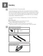
part 12J5289
4.3
4.4
(
)
Optional Finger-tighten the system-retaining screws
into the back
slide-rail bracket holes
on the back of the rack.
A
B
Repeat steps 4.2 and 4.3 for each
slide rail assembly.
A
E
D
D
F
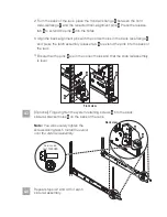
From the back of the rack, place the front rack flange
between the front
slide-rail flange
and the retracted front-alignment pins . Press the release
tab
to extend the pins
into the holes.
Align the back alignment pins with the correct holes in the back rack-flange
and press the latch assembly release tab
to extend the pins into the back of
the rack.
Ensure that the pins
are in the correct holes and that the slide rail assembly
is level.
E
F
D
A
D
E
A
D
2.
3.
4.
Front view
Note:
You will securely tighten the
screws during task 5
Install the server
onto the slide rail assembly.


