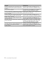
The
SMS
configuration
list
or
boot
sequence
selection
menu
shows
more
SCSI
devices
attached
to
a
controller/adapter
than
are
actually
attached.
A
device
may
be
set
to
use
the
same
SCSI
bus
ID
as
the
control
adapter.
Note
the
ID
being
used
by
the
controller/adapter
(this
can
be
checked
and/or
changed
through
an
SMS
utility),
and
verify
that
no
device
attached
to
the
controller
is
set
to
use
that
ID.
If
settings
do
not
appear
to
be
in
conflict:
1.
Go
to
“MAP
1548:
Processor
Subsystem
Problem
Isolation”
on
page
113.
2.
Replace
the
SCSI
cable.
3.
Replace
the
device.
4.
Replace
the
SCSI
adapter
Note:
In
a
″
twin-tailed
″
configuration
where
there
is
more
than
one
initiator
device
(normally
another
system)
attached
to
the
SCSI
bus,
it
may
be
necessary
to
use
SMS
utilities
to
change
the
ID
of
the
SCSI
controller
or
adapter.
The
System
Management
Services
menu
is
displayed.
If
you
are
loading
diagnostics
from
the
CD-ROM,
you
may
not
have
pressed
the
correct
key
when
you
were
trying
to
indicate
a
service
mode
IPL
of
the
diagnostic
programs.
If
this
is
the
case,
start
again
at
the
beginning
of
this
step.
If
you
are
sure
you
pressed
the
correct
key,
the
device
or
media
you
are
attempting
to
boot
from
may
be
faulty.
1.
If
you
are
using
the
hardware
management
console
(HMC)
or
an
ASCII
terminal:
v
Select
View
Error
Log
v
If
an
error
is
logged,
check
the
time
stamp.
v
If
the
error
was
logged
during
the
current
boot
attempt,
record
it.
v
Look
up
the
error
in
Chapter
5,
“Error
Code
to
FRU
Index,”
on
page
159
and
do
the
listed
action.
v
If
no
recent
error
is
logged
in
the
error
log,
go
to
step
3.
2.
If
you
are
using
a
keyboard
and
a
graphic
display
attached
to
the
system:
v
Select
View
Error
Log
v
If
an
error
is
logged,
check
the
time
stamp.
v
If
the
error
was
logged
during
the
current
boot
attempt,
record
it.
v
Look
up
the
error
in
Chapter
5,
“Error
Code
to
FRU
Index,”
on
page
159
v
If
no
recent
error
is
logged
in
the
error
log,
go
to
step
3.
3.
Try
to
boot
from
an
alternate
boot
device
connected
to
the
same
controller
as
the
original
boot
device.
If
the
boot
succeeds,
replace
the
original
boot
device
(for
removable
media
devices,
try
the
media
first).
4.
Go
to
“MAP
1548:
Processor
Subsystem
Problem
Isolation”
on
page
113.
Chapter
3.
Maintenance
Analysis
Procedures
(MAPs)
61
Summary of Contents for P 615 series
Page 1: ...pSeries 615 Service Guide SA38 0630 02 ERserver...
Page 2: ......
Page 3: ...pSeries 615 Service Guide SA38 0630 02 ERserver...
Page 12: ...x EserverpSeries 615 Service Guide...
Page 16: ...xiv EserverpSeries 615 Service Guide...
Page 18: ...xvi EserverpSeries 615 Service Guide...
Page 58: ...38 EserverpSeries 615 Service Guide...
Page 72: ...52 EserverpSeries 615 Service Guide...
Page 150: ...130 EserverpSeries 615 Service Guide...
Page 178: ...158 EserverpSeries 615 Service Guide...
Page 284: ...264 EserverpSeries 615 Service Guide...
Page 384: ...364 EserverpSeries 615 Service Guide...
Page 388: ...Model 6C3Parts 5 5 7 6 6 2 3 1 4 368 EserverpSeries 615 Service Guide...
Page 394: ...374 EserverpSeries 615 Service Guide...
Page 418: ...398 EserverpSeries 615 Service Guide...
Page 422: ...402 EserverpSeries 615 Service Guide...
Page 438: ...418 EserverpSeries 615 Service Guide...
Page 448: ...428 EserverpSeries 615 Service Guide...
Page 452: ...432 EserverpSeries 615 Service Guide...
Page 489: ......
Page 490: ...Printed in U S A October 2003 SA38 0630 02...
Page 491: ...Spine information pSeries 615 EserverpSeries 615 Service Guide SA38 0630 02...


