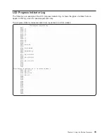

Please
wait....
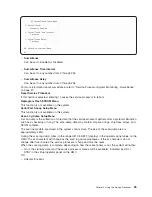
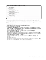
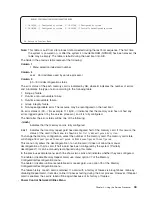
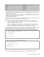
*****
Power
Trace
Data
Start
*****
00000000ffffffffffff0006158800a000061574a00000060200353700060210
031300060242000000060241040b0006110a0040000611090200000611020804
0000000000061102080b0006041000000006d0e3850000061103000000061109
02000006040200000006040200010006041000010006d0e38501000604100002
000000000006d0e385020006041000030006d0e3850300061580100000061540
03180006101116000006101116010006158010010007158156a0000711000010
00000000000910120000000910120001
*****
Power
Trace
data
End
*****
(Press
Return
to
Continue)
–
Start
SPCN
Flash
Update
This
option
is
not
available
on
this
system.
–
Display
Power
Subsystem
FRU
Code
Levels
This
option
is
not
available
on
this
system.
–
Power
Subsystem
Code
Update
via
the
Power
Control
Network
This
option
is
not
available
on
this
system.
–
Start
Power
Subystem
Code
Update:
This
option
is
not
available
on
this
system.
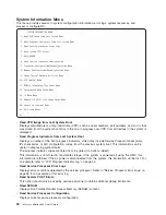
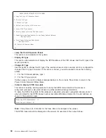
v
LED
Control
Menu
This
menu
displays
the
state
of
the
I/O
subsystem
disturbance/system
attention
LED.
Use
this
menu
to
toggle
the
attention/fault
LEDs
between
identify
(blinking)
and
off.
Option
1
is
only
available
when
the
system
is
in
the
error
state
(the
processor
subsystem
is
powered
on
and
the
service
processor
menus
are
available).
Option
1
is
not
available
when
the
system
is
in
standby.
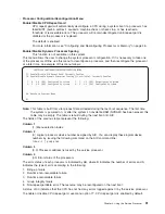
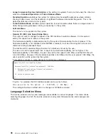
An
example
of
this
menu
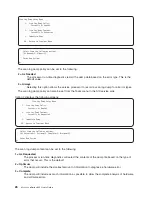
follows:
LED
Control
Menu
1.
Set/Reset
Identify
LED
state
2.
Clear
System
Attention
Indicator
98.
Return
to
Previous
Menu
0
>
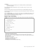
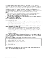
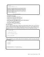
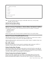
If
option
1
is
selected,
a
list
of
location
codes
of
the
I/O
subsystems
is
shown.
The
screen
will
be
similar
to
the
following:
LED
Control
Manu
1.
U1.9-P1
2.
U1.9-P2
3.
U1.5-P1
4.
U1.5-P2
Enter
number
corresponding
to
the
location
code,
or
press
Return
to
continue,
or
’x"
to
return
to
the
menu.
0>4
Chapter
4.
Using
the
Service
Processor
35
Summary of Contents for p 655 series
Page 1: ...pSeries 655 User s Guide SA38 0617 03 ERserver...
Page 2: ......
Page 3: ...pSeries 655 User s Guide SA38 0617 03 ERserver...
Page 10: ...viii Eserver pSeries 655 User s Guide...
Page 14: ...xii Eserver pSeries 655 User s Guide...
Page 16: ...xiv Eserver pSeries 655 User s Guide...
Page 24: ...6 Eserver pSeries 655 User s Guide...
Page 32: ...14 Eserver pSeries 655 User s Guide...
Page 36: ...18 Eserver pSeries 655 User s Guide...
Page 90: ...72 Eserver pSeries 655 User s Guide...
Page 144: ...126 Eserver pSeries 655 User s Guide...
Page 208: ...190 Eserver pSeries 655 User s Guide...
Page 214: ...196 Eserver pSeries 655 User s Guide...
Page 217: ......


