
If
one
of
the
devices
is
selected
using
the
index
number,
the
present
state
of
its
LED
will
be
displayed,
and
you
will
be
given
the
option
to
toggle
it
as
shown
in
these
example
screens.
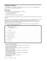
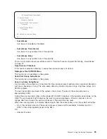
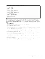
The
final
state
of
the
LED
will
then
be
displayed
whether
or
not
it
was
changed.
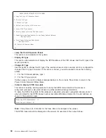
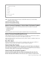
U1.5–P2
is
currently
in
the
OFF
state
Select
from
the
following
(1=IDENTIFY
ON,
2=IDENTIFY
OFF)
0>2
Please
wait
...
U1.5-P2
is
currently
in
the
OFF
state
(Press
Return
to
continue)
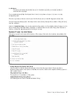
Option
2
is
not
available
on
this
system.
v
MCM/L3
Interposer
Plug
Count
Menu
Attention:
Do
not
power
on
the
system
when
in
this
menu.
Fully
exit
from
this
menu
before
powering
on
the
system.
This
menu
tracks
the
number
of
times
that
the
MCM
and
L3
cache
modules
have
been
plugged
into
the
system
backplane.
If
the
MCM
or
L3
cache
module
is
reseated
or
replugged,
the
plug
count
for
that
module
must
be
incremented
by
1.
If
the
plug
count
exceeds
the
limit
of
10
(reaches
11
or
greater),
a
450x
yyyy
or
4B2x
yyyy
error
with
a
detail
value
of
CFF0
that
calls
out
an
MCM
or
L3
cache
module
will
be
posted
in
the
service
processor
error
log.
The
FRU
should
be
replaced
during
a
deferred
service
call.
If
the
MCM
or
L3
cache
module
is
replaced,
or
installed
during
an
MES
upgrade,
the
plug
count
must
be
set
using
the
MCM/L3
Interposer
Plug
Count
menu.
If
the
plug
count
information
is
not
included
with
the
new
or
replacement
module,
enter
the
default
value
of
8
(7
for
the
manufacturing
process
and
1
for
the
installation
of
the
module
that
was
just
done).
If
the
plug
count
is
not
entered,
a
B1xx
4698
error
code,
with
a
detailed
value
of
E10B
or
E10C,
will
be
posted
in
the
service
processor
error
log.
If
the
service
processor
card
is
replaced,
the
plug
counts
are
retained.
However,
the
plug
count
menu
must
be
accessed
and
option
50,
Commit
the
values
and
write
to
the
VPD
,
must
be
executed,
so
that
the
plug
counts
are
revalidated.
If
the
counts
are
not
revalidated,
a
B1xx
4698
error
code,
with
a
detail
value
of
E10B
or
E10C,
will
be
posted
in
the
service
processor
error
log.
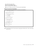
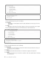
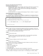
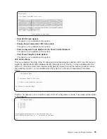
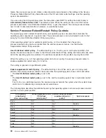
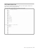
A
screen
similar
to
the
following
will
be
displayed.
MCM/L3
Interposer
Plug
Count
Menu
1.
L3_0:7
2.
L3_1:9
3.
MCM_0:8
4.
L3_3:7
5.
L3_2:7
50.
Commit
the
values
and
write
to
the
VPD
98.
Return
to
the
Previous
Menu
The
MCM
and
L3
cache
modules
are
shown
in
the
same
way
that
they
are
plugged
into
the
processor
subsystem
planar;
the
layout
shown
in
the
menu
represents
the
physical
location
as
seen
from
the
front
of
the
subsystem.
The
format
of
the
menu
entries
shown
above
is
the
menu
index
number,
followed
by
L3_xx,
followed
by
the
plug
count
after
the
colon.
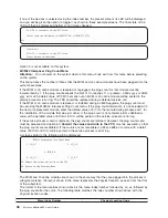
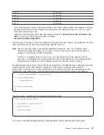
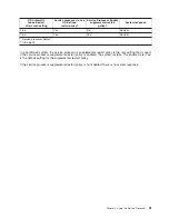
The
following
table
matches
the
index
number
shown
above
with
the
physical
location
codes.
Menu
Index
Number
Physical
Location
Code
36
Eserver
pSeries
655
User’s
Guide
Summary of Contents for p 655 series
Page 1: ...pSeries 655 User s Guide SA38 0617 03 ERserver...
Page 2: ......
Page 3: ...pSeries 655 User s Guide SA38 0617 03 ERserver...
Page 10: ...viii Eserver pSeries 655 User s Guide...
Page 14: ...xii Eserver pSeries 655 User s Guide...
Page 16: ...xiv Eserver pSeries 655 User s Guide...
Page 24: ...6 Eserver pSeries 655 User s Guide...
Page 32: ...14 Eserver pSeries 655 User s Guide...
Page 36: ...18 Eserver pSeries 655 User s Guide...
Page 90: ...72 Eserver pSeries 655 User s Guide...
Page 144: ...126 Eserver pSeries 655 User s Guide...
Page 208: ...190 Eserver pSeries 655 User s Guide...
Page 214: ...196 Eserver pSeries 655 User s Guide...
Page 217: ......