


111
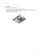
Parts/Test Point Locations
Parts/Test Point Locations ................................................................................................................................... 111
Introduction ............................................................................................................................................................. 112
Layout of System Board of Machine Types 2194 (Italy), 2197 and 6344 (EMEA/AP)............................................. 113
Jumper Settings of the System Board of Machine Types 2194 (Italy), 2197 and 6344 (EMEA/AP)............... 114
Connectors and Functions of System Board of Machine Types 2194 (Italy), 2197 and 6344 (EMEA/AP)..... 115
Layout of System Board of Machine Type 6344 (US/Canada/LA) .......................................................................... 116
Connectors and Functions of System Board of Machine Type 6344 (US/Canada/LA) .................................. 117
Layout of System Board of Machine Types 2193 and 2196.................................................................................... 118
Jumper Settings of the System Board of Machine Types 2193 and 2196...................................................... 119
Connectors and Functions of System Board of Machine Types 2193 and 2196............................................ 120
Layout of System Board of Machine Types 2194 and 6345.................................................................................... 121
Jumper and Connector Settings of System Board of Machine Types 2194 and 6345 ................................... 122
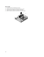
Power Supply Cable Connector Specifications ....................................................................................................... 127
Main Output Pin Assignment.......................................................................................................................... 128
Factory-Installed Modem Card Layout .................................................................................................................... 130
Factory-Installed Modem Card Connector Functions ..................................................................................... 130
3.5-In. Hard Disk Drive Jumper Locations & Settings ............................................................................................. 131
CD-ROM Drive........................................................................................................................................................ 132
CD-ROM Emergency-exit .............................................................................................................................. 132
CD-ROM Drive Rear Panel Connectors and Features................................................................................... 133
CD-ROM Drive Jumper Settings .................................................................................................................... 133
DIMM Configurations .............................................................................................................................................. 134
System Board Connector Pin Signals ..................................................................................................................... 135
Monitor Port Signals....................................................................................................................................... 135
Serial Port Signals ......................................................................................................................................... 135
Parallel Port Signals....................................................................................................................................... 135
Mouse Port Signals ........................................................................................................................................ 135
Keyboard Port Signals ................................................................................................................................... 136
Diskette Drive Cable Connector Signals ........................................................................................................ 137
IDE Cable Connector Signals ........................................................................................................................ 138
Copyright IBM Corp. 2000
Summary of Contents for PC 300
Page 11: ...11...
Page 12: ...12...
Page 13: ...13...
Page 14: ...14...
Page 15: ...15...
Page 25: ...25...
Page 26: ...26...
Page 27: ...27...
Page 34: ...34...
Page 86: ...86...
Page 110: ...110...
Page 129: ...129 Hard Drive or CD ROM Power Cable Connector 3 5 In Diskette Drive Power Cable Connector...
Page 139: ...139 Safety Inspection Guide General Guidelines 140...


