


67
Troubleshooting
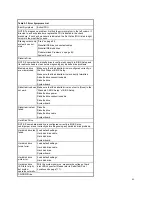
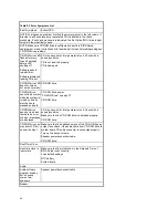
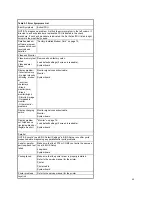
Failing Parts or Assemblies: The check procedures generally help you trace a problem to one part or assembly. The last step
of the specific check procedure you are using indicates that a part or assembly is failing. You should inspect the part or
assembly before you decide to replace it. It might be loose, dirty, or in need of a small repair. The check procedures might
lead you to two, or even three, possible failing parts or assemblies. The parts that might be failing are listed in order of the
most probable failure. Also, the FRU parts are defined as replaced units and are not repaired in the field.
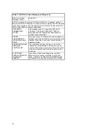
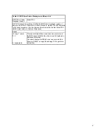
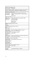
Measuring Voltages: Some check procedure steps instruct you to measure voltages on cable plugs and electronic board
connectors. If you are asked to measure voltage at several places on a plug or connector, a chart next to or near the
instruction indicates the number of the plug or connector, the pin numbers you should measure, the signal name, and the
correct voltage for the condition you are measuring. Measure the voltage only at the pins listed in the chart. Remember to set
the meter on the correct scale and to put the meter leads in the correct position for the voltage you are asked to measure.
NOTE:
Use frame ground as the ground reference. Attach the black (ground) lead of meter to frame ground, except wher
specified otherwise.
Summary of Contents for PC 300
Page 11: ...11...
Page 12: ...12...
Page 13: ...13...
Page 14: ...14...
Page 15: ...15...
Page 25: ...25...
Page 26: ...26...
Page 27: ...27...
Page 34: ...34...
Page 86: ...86...
Page 110: ...110...
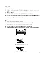
Page 129: ...129 Hard Drive or CD ROM Power Cable Connector 3 5 In Diskette Drive Power Cable Connector...
Page 139: ...139 Safety Inspection Guide General Guidelines 140...


