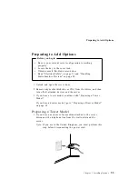
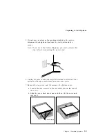
Preparing to Add Options
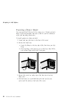
Preparing a Drawer Model
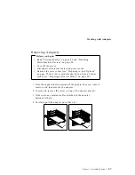
You can install the PC Server 325 in a drawer in a 19-inch rack unit.
Refer to the documentation that comes with the rack for additional
safety and operating information.
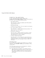
To install options in a drawer model:
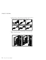
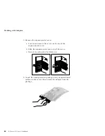
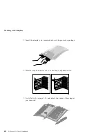
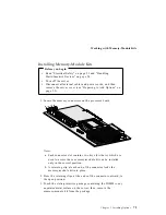
1. Unlock and open the door on the front of the server.
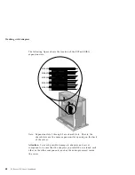
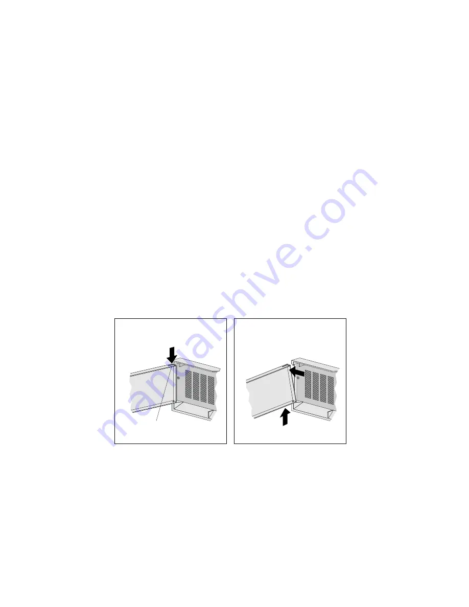
2. Remove the front door:
a. Locate the flange on the top edge of the front door, near the
hinge.
b. Press the flange while pressing out on the door; then lift the
door off the hinge and store in a safe place.
Flange
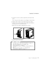
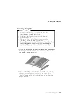
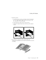
3. Remove the screws on either side of the front bezel, and set
them aside.
4. Pull the drawer out until both slide rails lock, and you can
easily reach the cables on the back of the server.
58
PC Server 325 User's Handbook
Summary of Contents for PC Server 325
Page 1: ...PC Server 325 User s Handbook IBM...
Page 6: ...vi PC Server 325 User s Handbook...
Page 10: ...Laser Compliance Statement x PC Server 325 User s Handbook...
Page 136: ...Updating the Server Configuration 122 PC Server 325 User s Handbook...
Page 212: ...Resolving Configuration Conflicts 198 PC Server 325 User s Handbook...
Page 238: ...Installed Device Records 224 PC Server 325 User s Handbook...
Page 287: ......
Page 288: ...IBM Part Number 76H8831 Printed in U S A September 1996 76H8831...


