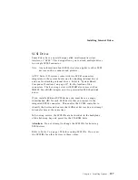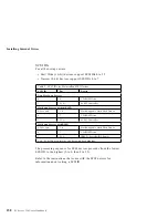
Working with Memory-Module Kits
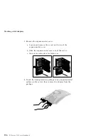
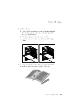
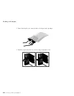
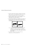
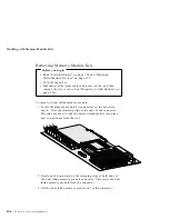
3. Touch the static-protective package containing the dual inline
memory module to any unpainted metal surface on the server;
then, remove the memory-module kit from the package.
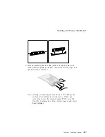
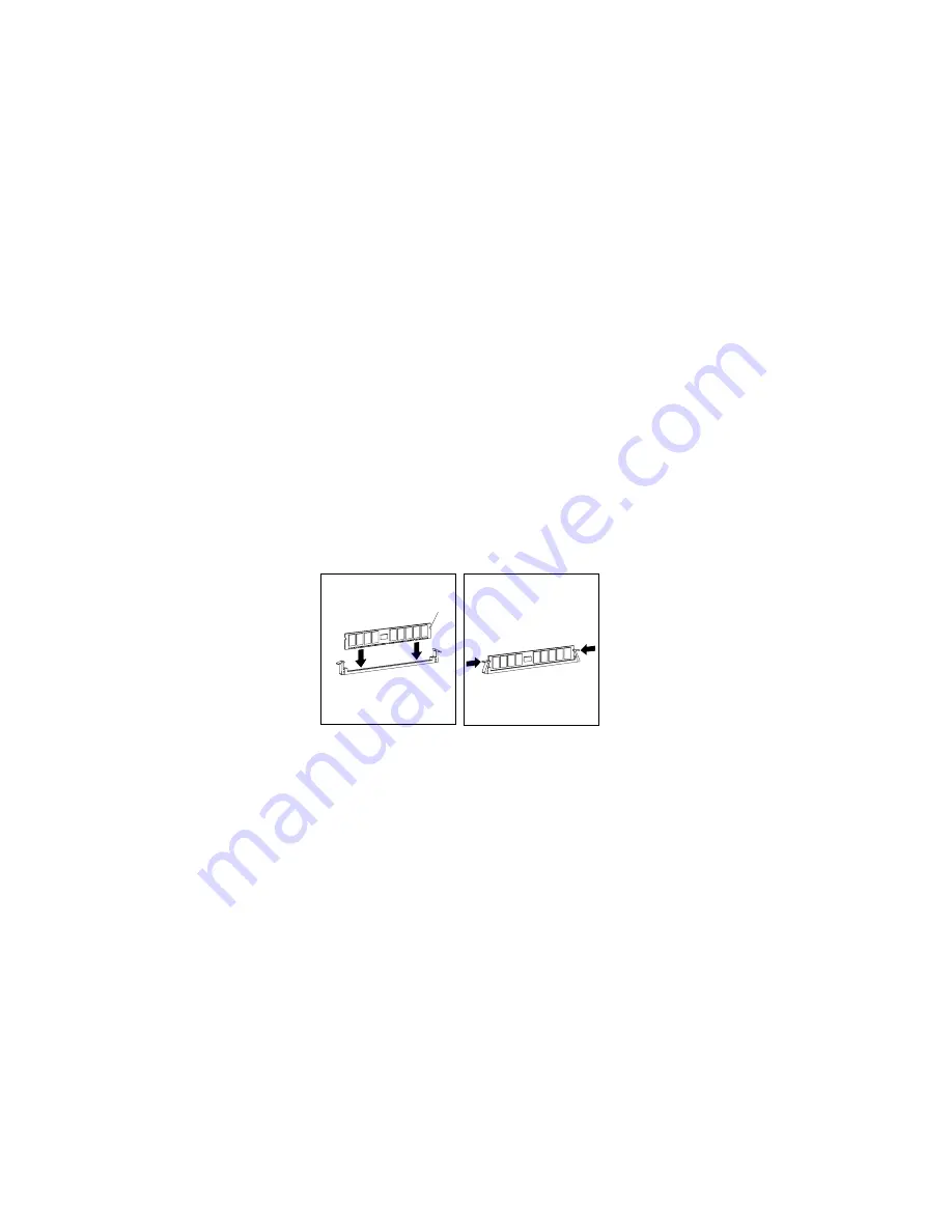
4. Position the DIMM so that the two key slots (openings in the
connector pins) on the bottom edge align with the
corresponding sections in the connector.
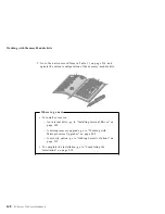
5. After aligning the DIMM, push the DIMM firmly straight down
into the connector. (The retaining clips on both sides of the
connector automatically come up into the notches on the sides
of the DIMM.)
Notch
Note: Adding or removing memory-module kits changes the
configuration information in the server. When you
restart the server, the system displays a POST error 164.
Start the Configuration/Setup utility program and select
Save Settings
.
6. Go to Table 11 on page 336 and update the current
configuration of the memory-module kits.
144
PC Server 330 User's Handbook
Summary of Contents for PC Server 330
Page 1: ...PC Server 330 User s Handbook IBM...
Page 6: ...vi PC Server 330 User s Handbook...
Page 10: ...x PC Server 330 User s Handbook...
Page 32: ...18 PC Server 330 User s Handbook...
Page 100: ...86 PC Server 330 User s Handbook...
Page 134: ...120 PC Server 330 User s Handbook...
Page 240: ...Updating the Server Configuration 226 PC Server 330 User s Handbook...
Page 326: ...Resolving Configuration Conflicts 312 PC Server 330 User s Handbook...
Page 382: ...IBM Part Number 76H8834 Printed in U S A September 1996 76H8834...


