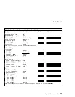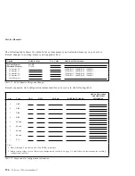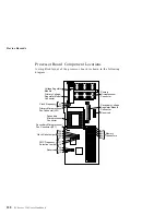
Device Records
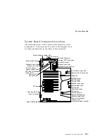
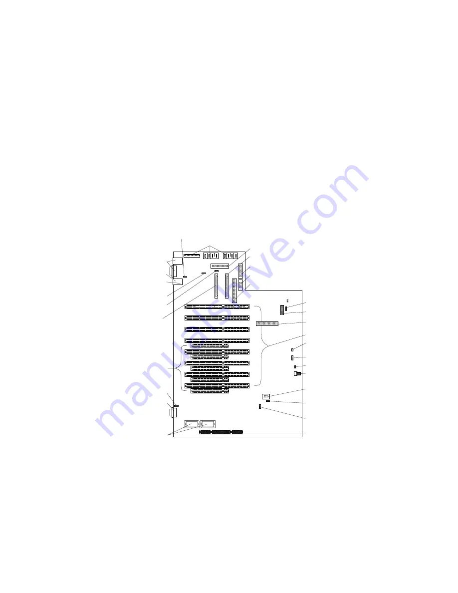
System Board Component Locations
The following layout of the system board identifies server
components. You might need to refer to the diagram when
recording information in the tables in this appendix.
Ethernet Enable Jumper (J22)
2
3
4
5
6
7
8
9
1
2
3
4
5
Ethernet Connectors
Mouse Connector
Keyboard Connector
SCSI Controller
Enable Jumper (J26)
SCSI Bus Termination
Jumper (J38)
External SCSI
Connector (J29)
PCI Slots
Video Enable (J25)
Video Connector
Video RAM Sockets
Processor Board Connector
Power-On Password
Jumper (J12)
System Management
Enable Jumper (J49)
C2 Security
Cable Connector
System Fan
Power Connector
System Reset (J27)
Speaker Connector
EISA/ISA Slots
Reserved
Flash Enable
Jumper (J39)
Operator Panel Connector
-5V Select Jumper (J33)
Diskette Drive Connector
Infrared Connector
Serial Connector
Internal SCSI Connector
Parallel Connector
Power Connectors
Appendix B. Server Records
337
Summary of Contents for PC Server 330
Page 1: ...PC Server 330 User s Handbook IBM...
Page 6: ...vi PC Server 330 User s Handbook...
Page 10: ...x PC Server 330 User s Handbook...
Page 32: ...18 PC Server 330 User s Handbook...
Page 100: ...86 PC Server 330 User s Handbook...
Page 134: ...120 PC Server 330 User s Handbook...
Page 240: ...Updating the Server Configuration 226 PC Server 330 User s Handbook...
Page 326: ...Resolving Configuration Conflicts 312 PC Server 330 User s Handbook...
Page 382: ...IBM Part Number 76H8834 Printed in U S A September 1996 76H8834...

