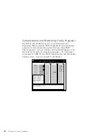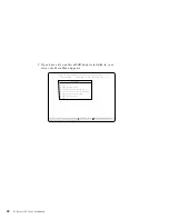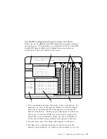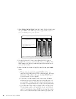
list indicates the physical drive state and the array in which the
drive is grouped. For example, in the illustration, the drive in
Channel 2, Bay 1 has a drive state of ONL (online) and is a part
of Array B. Selections are made from this list to determine
which bays (hard disk drives) are in your arrays.
Notes:
a. The Bay/Array area on the screen does not reflect the
physical configuration of the server. In your server, you
have one “bank” of hot-swap drive bays, bank C. The
default numbering for the hot-swap drive bays is numbered
1 through 6 (from top to bottom). Refer to “Installing
Internal Drives” on page 149. for the physical location of
the hard disk drives.
b. The internal drives in your server come connected to
Internal Channel 3 of the ServeRAID adapter.
To attach external devices to your server, you can use the
External Channel 1 connector. You can also attach external
devices to a separately purchased cable, and then connect
the cable from the Internal Channel 2 connector on the
adapter and out the back of your server, either through the
knockout panel or by removing an expansion slot cover.
c. The Bay Number corresponds to the SCSI ID of the device
plus 1.
4. The Array list indicates the array ID and the size (in megabytes)
of the array. When a drive is being rebuilt, this area and the
Logical Drive list area show the progression of the rebuild
process.
5. The Logical Drive list identifies the logical drive installed (for
example, A1), including the size of the logical drive, the RAID
level assigned to the logical drive, the date the logical drive was
created, the status of the logical drive, and its write policy.
Note: Logical drives are numbered 0 through 7 in ascending
order from top to bottom. They are position dependent,
for example, logical drive 3 will always display on the
fourth line (B0) even if logical drives 0, 1, and 2 are
deleted.
32
PC Server 330 User's Handbook
Summary of Contents for PC Server 330
Page 1: ...PC Server 330 User s Handbook IBM...
Page 6: ...vi PC Server 330 User s Handbook...
Page 10: ...x PC Server 330 User s Handbook...
Page 32: ...18 PC Server 330 User s Handbook...
Page 100: ...86 PC Server 330 User s Handbook...
Page 134: ...120 PC Server 330 User s Handbook...
Page 240: ...Updating the Server Configuration 226 PC Server 330 User s Handbook...
Page 326: ...Resolving Configuration Conflicts 312 PC Server 330 User s Handbook...
Page 382: ...IBM Part Number 76H8834 Printed in U S A September 1996 76H8834...


