Choosing a Mode of Operation
Configuration 2
System Bus
10BaseT
HUB 7
10BaseT
HUB 8
10BaseT
HUB 4
Net 1
Net 2
Net 2
Net 1
Net 2
LAN Driver
Protocol
Net 1
Port 1
Port 2
Port 3
Port 4
Port 1
Port 2
Port 3
Port 4
Port 1 Port 2 Port 3 Port 4
LAN Driver
Port 1 Port 2 Port 3 Port 4
10BaseT
HUB 3
VNET
VNET
Switch 1
Switch 2
Virtual Network Layer
Router
10BaseT
10BaseT
HUB 1
HUB 2
10BaseT
10BaseT
HUB 5
HUB 6
Adapter 1
Adapter 2
Net 2
Net 1
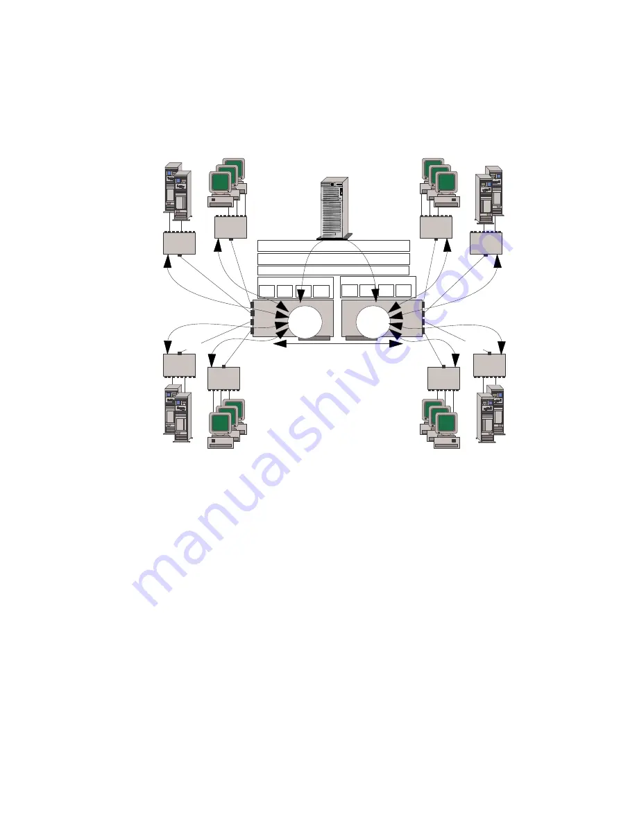
This illustration shows:
A configuration of two network numbers (Net 1 and Net 2).
An 8-port network with two PeerMaster adapters (Adapter 1
and Adapter 2), each configured as an independent VNET (two
VNETs).
The curved arrow that passes through the LAN drivers, protocol
stacks, and router in the server represents the connection
between the two subnets (Net 1 and Net 2). Cross-subnet
traffic, such as traffic from Net 1 to Net 2, must be forwarded
by a router. The router can be internal to the server or an
external stand-alone device.
Each VNET can represent a separate department or workgroup.
The four switched ports within each VNET provide a multisegment
workgroup environment. Isolating the two VNETs by way of the
Chapter 4. Configuring the PeerMaster Adapter
139
Summary of Contents for PC Server 520
Page 1: ...PC Server 520 User s Handbook for PCI Micro Channel IBM...
Page 86: ...Installation Checklist 70 PC Server 520 User s Handbook for PCI Micro Channel...
Page 146: ...Using the Mini Configuration Program 130 PC Server 520 User s Handbook for PCI Micro Channel...
Page 190: ...Using the SCSISelect Utility Program 174 PC Server 520 User s Handbook for PCI Micro Channel...
Page 385: ...Installing Additional Test Programs 207 CMD 3 Chapter 7 Solving Problems 369...
Page 438: ...IBM Part Number 78H6336 Printed in U S A May 1996 78H6336...


