Attaching Network Cables to Your Adapter
Attaching Network Cables to Your Adapter
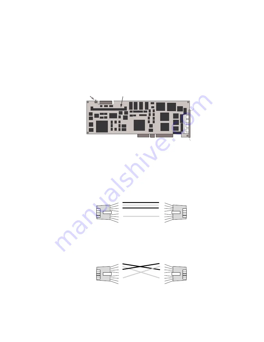
The following illustration shows the location of the four Ethernet
connectors on the PeerMaster adapter. The top connector on the
adapter is port 1; the bottom connector is port 4.
Port 1
Port 2
Port 3
Port 4
DRAM SIMM Socket
Diagnostic Error LED
Attention
: Ensure that you do not externally join ports of adapters
(using bridges, switches, or concentrators).
You can connect two types of network cables to the PeerMaster
adapter: straight-through and crossover.
Use straight-through cables when connecting your adapter to an
external 10Base-T concentrator hub.
1
2
3
4
5
6
7
8
1
2
3
4
5
6
7
8
Straight-through
Use crossover cables to directly connect your PeerMaster adapter to
another 10Base-T device, such as a workstation, server, or another
adapter. Crossover cables create dedicated segments. A dedicated
segment is two point-to-point devices connected to a dedicated link.
1
2
3
4
5
6
7
8
1
2
3
4
5
6
7
8
Crossover
Chapter 4. Configuring the PeerMaster Adapter
145
Summary of Contents for PC Server 520
Page 1: ...PC Server 520 User s Handbook for PCI Micro Channel IBM...
Page 86: ...Installation Checklist 70 PC Server 520 User s Handbook for PCI Micro Channel...
Page 146: ...Using the Mini Configuration Program 130 PC Server 520 User s Handbook for PCI Micro Channel...
Page 190: ...Using the SCSISelect Utility Program 174 PC Server 520 User s Handbook for PCI Micro Channel...
Page 385: ...Installing Additional Test Programs 207 CMD 3 Chapter 7 Solving Problems 369...
Page 438: ...IBM Part Number 78H6336 Printed in U S A May 1996 78H6336...


