Changing Jumper Settings
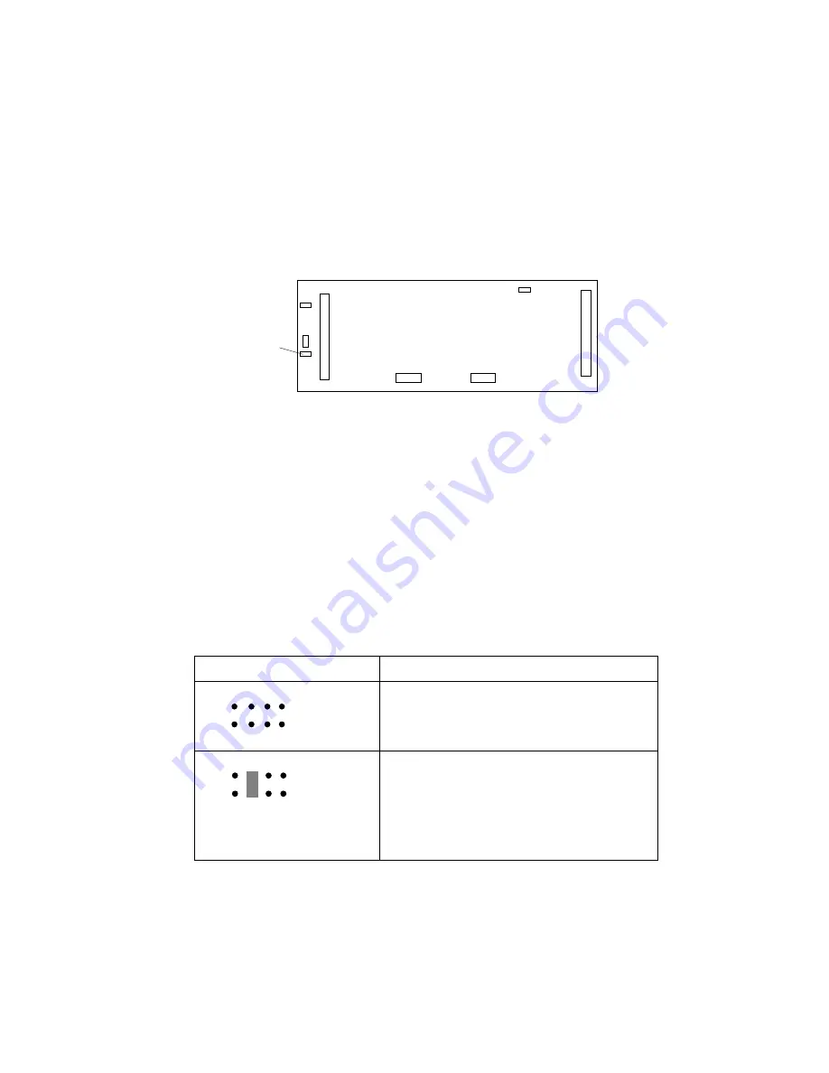
Setting Backplane SCSI ID Jumpers (J12)
The SCSI ID address jumper, a pin block with four pairs of pins
(J12), is located on the rear of the backplanes in banks C, D, and E.
The default, no jumper installed, sets the addresses to LO.
J12
Each of the 16-bit SCSI connectors on the ServeRAID adapter and on
the system board supports up to 15 devices. Thus, each supports
SCSI IDs of 0 through 14.
When you daisy-chain two backplanes in a disk-array model, one
backplane address jumper (for example, Bank C) must be set to LO,
defining the SCSI IDs as 0 through 5. The backplane that is
daisy-chained to Bank C (in this example, bank D) must be set to
HI, defining the SCSI IDs as 8 through 13.
The following table summarizes the jumper settings for the SCSI ID
jumper (J12).
Jumper Position
Description
LO
J12
5 7
4 6
2
8
3
1
No jumper installed, sets SCSI IDs to
low, starting from 0 (bay 1) to 5 (bay 6).
This is the default setting for Bank C.
HI
J12
5 7
4 6
2
8
3
1
Sets SCSI IDs to high, starting from
8 (bay 1) to 13 (bay 6). Use this setting
when you daisy-chain two banks, or
when your configuration requires you to
define some of the hot-swap drives with
high IDs.
274
PC Server 520 User's Handbook for PCI/Micro Channel
Summary of Contents for PC Server 520
Page 1: ...PC Server 520 User s Handbook for PCI Micro Channel IBM...
Page 86: ...Installation Checklist 70 PC Server 520 User s Handbook for PCI Micro Channel...
Page 146: ...Using the Mini Configuration Program 130 PC Server 520 User s Handbook for PCI Micro Channel...
Page 190: ...Using the SCSISelect Utility Program 174 PC Server 520 User s Handbook for PCI Micro Channel...
Page 385: ...Installing Additional Test Programs 207 CMD 3 Chapter 7 Solving Problems 369...
Page 438: ...IBM Part Number 78H6336 Printed in U S A May 1996 78H6336...


