140
IBM Power 595 Technical Overview and Introduction
performance. The other Power models deliver balanced performance using only a single
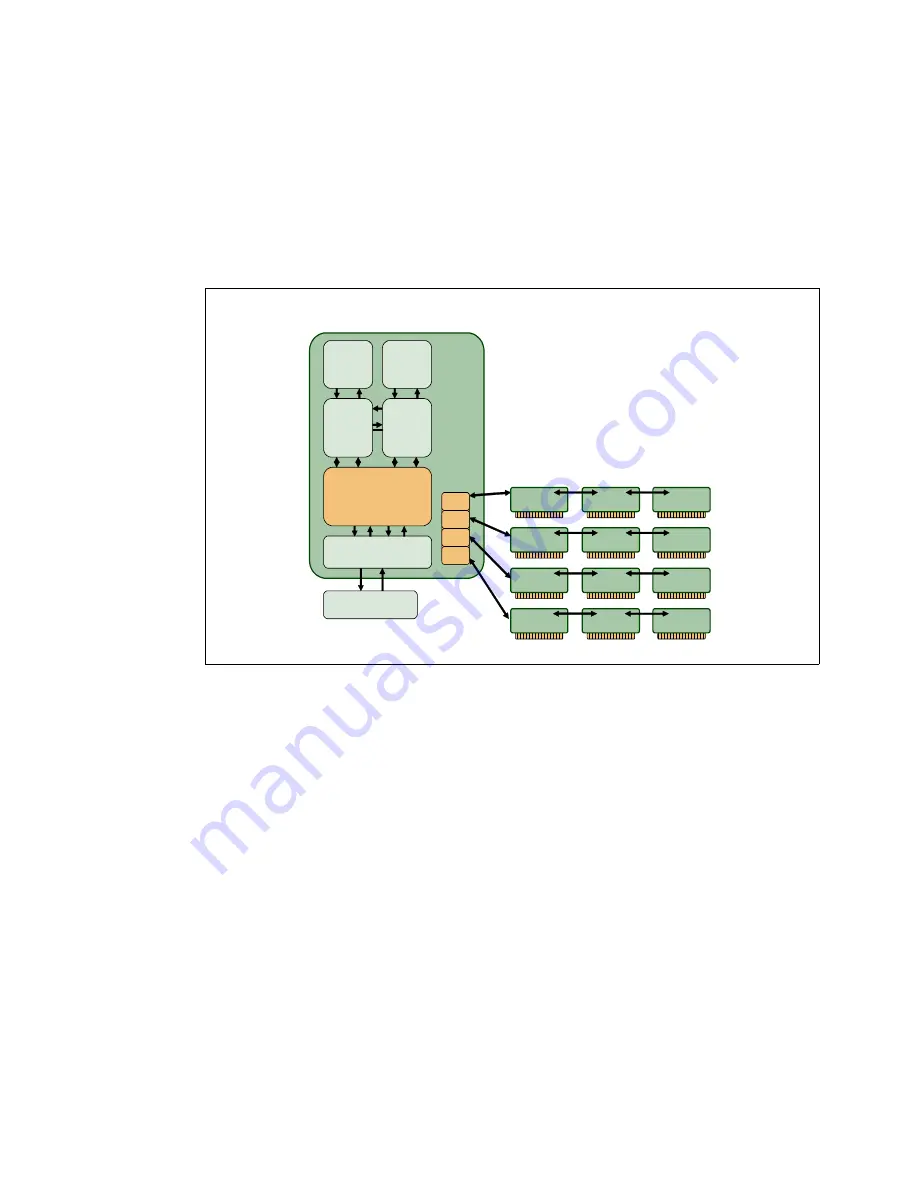
memory controller. Some models also employ an L3 cache controller. A memory controller on
a POWER6 process-based system is designed with four ports. Each port connects up to
three DIMMS using a daisy-chained bus. The memory bus supports ECC checking on data,
addresses, and command information. A spare line on the bus is also available for repair
using a self-healing strategy. In addition, ECC checking on addresses and commands is
extended to DIMMs on DRAMs. Because it uses a daisy-chained memory-access topology,
this system can deconfigure a DIMM that encounters a DRAM fault, without deconfiguring the
bus controller, even if the bus controller is contained on the DIMM.
Figure 4-5 Memory control hierarchy
Memory deconfiguration
Defective memory discovered at boot time is automatically switched off, unless it is already
the minimum amount required to boot. If the service processor detects a memory fault at boot
time, it marks the affected memory as bad so it is not to be used on subsequent reboots
(memory persistent deallocation).
If the service processor identifies faulty memory in a server that includes CoD memory, the
POWER Hypervisor attempts to replace the faulty memory with available CoD memory. Faulty
resources are marked as deallocated and working resources are included in the active
memory space. Because these activities reduce the amount of CoD memory available for
future use, repair of the faulty memory should be scheduled as soon as is convenient.
Upon reboot, if not enough memory is available to meet minimum partition requirements, the
POWER Hypervisor reduces the capacity of one or more partitions. The HMC receives
notification of the failed component, triggering a service call.
Defective memory discovered at IPL time is switched off by a server, as follows:
If a memory fault is detected by the service processor at boot time, the affected memory
will be marked as bad and will not be used on this or subsequent IPLs (memory persistent
deallocation).
POWER6
Core
POWER6
Core
4 MB
L2
4 MB
L2
Fabric bus
controller
GX bus Cntrl
Ctrl
DIMM
Ctrl
DIMM
Ctrl
DIMM
Ctrl
DIMM
Ctrl
DIMM
Ctrl
DIMM
Ctrl
DIMM
Ctrl
DIMM
Ctrl
DIMM
Ctrl
DIMM
Ctrl
DIMM
Ctrl
DIMM
GX+ Bridge
Port
Port
Port
Port
Memory
controller
Summary of Contents for Power 595
Page 2: ......
Page 120: ...108 IBM Power 595 Technical Overview and Introduction...
Page 182: ...170 IBM Power 595 Technical Overview and Introduction...
Page 186: ...174 IBM Power 595 Technical Overview and Introduction...
Page 187: ......


