Chapter 2. Architectural and technical overview
69
Consistent power management for all Power System offerings from BladeCenter to Power
595.
2.4 System cooling
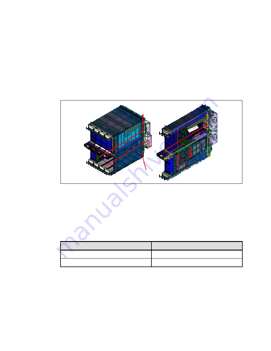
CEC cooling is provided by up to four air-moving devices (high-pressure, high-flow blowers)
that mount to a plenum on the rear of the CEC cage (refer to Figure 2-3 on page 40). Air is
drawn through all plugged nodes in parallel. In a hot room or under certain fault conditions,
blower speed can increase to maintain sufficient cooling. Figure 2-25 shows air flow through
the CEC.
Figure 2-25 CEC internal air flow
Four motor drive assemblies (MDAs) mount on the four air moving devices (AMD™), as
follows. A light strip LED identifies AMD and MDA.
MDA 1 & 3 are powered by a Y-cable from the BPC – Connector J10.
MDA 2 & 4 are powered by a Y-cable from the BPC – Connector J11.
Table 2-11 details the blower population
Table 2-11 Books
2.5 Light strips
The Power 595 server uses a front and back light strip for service. The front and rear light
strips each have redundant control modules that can receive input from either System
Controller (SC).
Processor book quantity
AMD
1 or 2 processor books
A1 and A3
3 or more processor books
A1, A2, A3, A4
Air Movement Device
AMDs (4x )
PLENUM
Air
Flo
w
Air Movement Device
AMDs (4x )
PLENUM
Air
Flo
w
Summary of Contents for Power 595
Page 2: ......
Page 120: ...108 IBM Power 595 Technical Overview and Introduction...
Page 182: ...170 IBM Power 595 Technical Overview and Introduction...
Page 186: ...174 IBM Power 595 Technical Overview and Introduction...
Page 187: ......


