background image

84


IBM Power 595 Technical Overview and Introduction

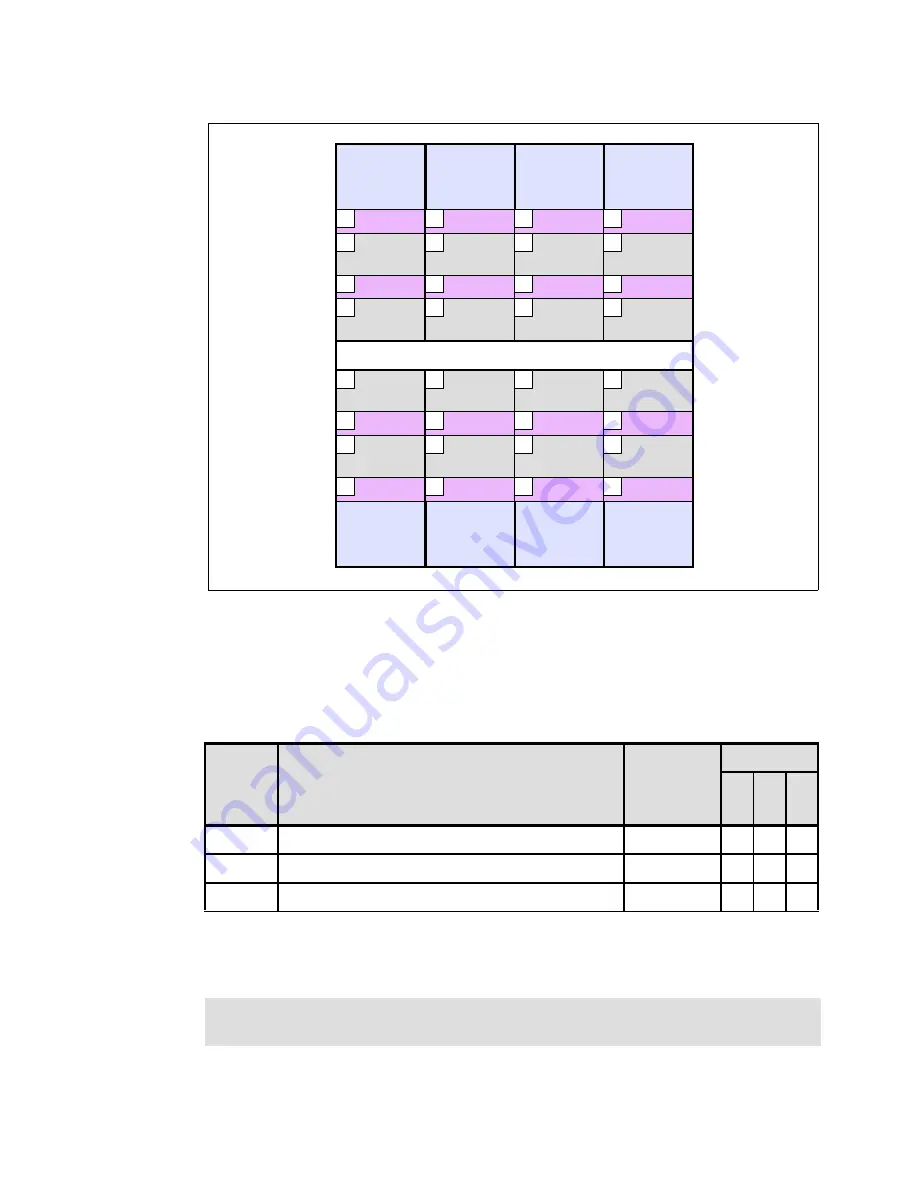
Figure 2-35   I/O hub installation sequence

2.8.2  Internal I/O drawers

The internal I/O drawers (24 inches) provide storage and I/O connectivity for the 595 server. 
The available internal I/O drawers are listed in Table 2-20

Table 2-20   Internal I/O drawers

I/O drawers #5791 and #5797 (with repeater) are supported in the system (CEC) rack, 
powered expansion racks, and nonpowered expansion racks. I/O drawer #5798 (without 
repeater) is only supported in the system rack.

Node P2

Plug seq. 4

Wide

Narrow

Wide

Narrow

12

28

4

20

Node P3

Plug seq. 7

Wide

Narrow

Wide

Narrow

15

31

7

23

Node P4

Plug seq. 8

Wide

Narrow

Wide

Narrow

16

32

8

24

Node P5

Plug seq. 2

Wide

Narrow

Wide

Narrow

10

26

2

18

Plug seq. 3

Node P6

Narrow

3

Wide

27

Narrow

11

Wide

19

Mid-plane

Plug seq. 5

Node P7

Narrow

5

Wide

29

Narrow

13

Wide

21

Plug seq. 6

Node P8

Narrow

6

Wide

30

Narrow

14

Wide

22

Plug seq. 1

Node P9

Narrow

1

Wide

25

Narrow

9

Wide

17

Node P2

Plug seq. 4

Wide

Narrow

Wide

Narrow

12

28

4

20

Node P3

Plug seq. 7

Wide

Narrow

Wide

Narrow

15

31

7

23

Node P4

Plug seq. 8

Wide

Narrow

Wide

Narrow

16

32

8

24

Node P5

Plug seq. 2

Wide

Narrow

Wide

Narrow

10

26

2

18

Node P2

Plug seq. 4

Wide

Narrow

Wide

Narrow

12

28

4

20

Node P2

Plug seq. 4

Wide

Narrow

Wide

Narrow

12

28

4

20

Node P3

Plug seq. 7

Wide

Narrow

Wide

Narrow

15

31

7

23

Node P3

Plug seq. 7

Wide

Narrow

Wide

Narrow

15

31

7

23

Node P4

Plug seq. 8

Wide

Narrow

Wide

Narrow

16

32

8

24

Node P4

Plug seq. 8

Wide

Narrow

Wide

Narrow

16

32

8

24

Node P5

Plug seq. 2

Wide

Narrow

Wide

Narrow

10

26

2

18

Node P5

Plug seq. 2

Wide

Narrow

Wide

Narrow

10

26

2

18

Plug seq. 3

Node P6

Narrow

3

Wide

27

Narrow

11

Wide

19

Plug seq. 3

Node P6

Narrow

3

Narrow

3

Wide

27

Wide

27

Narrow

11

Narrow

11

Wide

19

Wide

19

Mid-plane

Plug seq. 5

Node P7

Narrow

5

Wide

29

Narrow

13

Wide

21

Plug seq. 5

Node P7

Narrow

5

Narrow

5

Wide

29

Wide

29

Narrow

13

Narrow

13

Wide

21

Wide

21

Plug seq. 6

Node P8

Narrow

6

Wide

30

Narrow

14

Wide

22

Plug seq. 6

Node P8

Narrow

6

Narrow

6

Wide

30

Wide

30

Narrow

14

Narrow

14

Wide

22

Wide

22

Plug seq. 1

Node P9

Narrow

1

Wide

25

Narrow

9

Wide

17

Plug seq. 1

Node P9

Narrow

1

Narrow

1

Wide

25

Wide

25

Narrow

9

Narrow

9

Wide

17

Wide

17

Feature

Description

Connection 
Adapter

Support

AI

X

IBM i

Lin

u

x

#5791

I/O drawer, 20 slots, 16 disk bays

1814

9

9

#5797

12x I/O drawer, 20 slots, 16 disk bays, with repeater

1816

9

9

9

#5798

12x I/O drawer, 20 slots, 16 disk bays, no repeater

1816

9

9

9

Note:

 I/O drawers #5797 and #5798 have a planned availability date of November 21, 

2008.

Summary of Contents for Power 595

Page 1: ...ver IBM Power 595 Technical Overview and Introduction Charlie Cler Carlo Costantini PowerVM virtualization technology including Live Partition Mobility World class performance and flexibility Mainfram...

Page 2: ......

Page 3: ...International Technical Support Organization IBM Power 595 Technical Overview and Introduction August 2008 REDP 4440 00...

Page 4: ...ghts Use duplication or disclosure restricted by GSA ADP Schedule Contract with IBM Corp First Edition August 2008 This edition applies to the IBM Power Systems 595 9119 FHA IBMs most powerful Power S...

Page 5: ...Linux for Power I O considerations 16 1 3 6 Hardware Management Console models 17 1 3 7 Model conversion 18 1 4 Racks power and cooling 29 1 4 1 Door kit 30 1 4 2 Rear door heat exchanger 31 1 4 3 Pow...

Page 6: ...drawer to I O hub cabling sequence 90 2 9 PCI adapter support 92 2 9 1 LAN adapters 93 2 9 2 SCSI adapters 93 2 9 3 iSCSI 94 2 9 4 SAS adapters 94 2 9 5 Fibre Channel adapters 95 2 9 6 Asynchronous WA...

Page 7: ...Continuous field monitoring 133 4 2 Availability 134 4 2 1 Detecting and deallocating failing components 134 4 2 2 Special uncorrectable error handling 141 4 2 3 Cache protection mechanisms 142 4 2 4...

Page 8: ...IBM Power 595 Technical Overview and Introduction 4 6 Cluster solution 169 Related publications 171 IBM Redbooks 171 Other publications 171 Online resources 172 How to get Redbooks 173 Help from IBM 1...

Page 9: ...ditions of the publication IBM may make improvements and or changes in the product s and or the program s described in this publication at any time without notice Any references in this information to...

Page 10: ...books logo RS 6000 System i System i5 System p System p5 System Storage System x System z Tivoli TotalStorage WebSphere Workload Partitions Manager z OS The following terms are trademarks of other com...

Page 11: ...nce that offers a detailed technical description of the 595 system This Redpaper does not replace the latest marketing materials tools and other IBM publications available for example at the IBM Syste...

Page 12: ...erg Doug Szerdi Dave Williams IBM Austin Mark Applegate Avnet Become a published author Join us for a two to six week residency program Help write a book dealing with specific products or solutions wh...

Page 13: ...the most cost effective and flexible IT infrastructure while achieving the best application performance and increasing the speed of deployment of new applications and services As the most powerful me...

Page 14: ...to four GX based I O hub adapter cards RIO 2 or 12x for connection to system I O drawers Two Node Controller NC service processors primary and redundant One or two optional Powered Expansion Racks eac...

Page 15: ...t PCI X Adapter slots 5791 RIO 2 drawer 20 PCI X 133 MHz 240 per system 5797 or 5798 drawer 14 PCI X 2 0 266 MHz 6 PCI X 133 MHz 600 per system I O ports 4 GX adapter ports per processor book 32 per s...

Page 16: ...ower supplies and cooling fans Dynamic Processor Deallocation Dynamic deallocation of logical partitions and PCI bus slots Extended error handling on PCI X slots Redundant power supplies and cooling f...

Page 17: ...ice clearances for a two rack configuration with acoustical doors Frame With integrated battery backup Without integrated battery backup A Frame system rack 1542 kg 3400 lb 1451 kg 3200 lb A Frame pow...

Page 18: ...for the Power 595 server Table 1 6 Power 595 server operating environment specifications Important If the Power 595 server must pass through a doorway opening less than 2 02 meters 79 5 inches you sho...

Page 19: ...9296 8 2 bels with acoustical doors Sound pressure Declared A weighted one meter sound pressure level per ISO 9296 79 decibels with slim line doors Declared A weighted one meter sound pressure level...

Page 20: ...9W IEC60309 30 A type 430R7W IEC60309 30 A type 430R7W 5 0 GHz Server System Rating 48 A 63 A 24 A 34 A Plug rating 60 A 100 A 30 A 60 A Recommend circuit breaker rating 60 A 100 A 30 A 60 A Cord size...

Page 21: ...GHz server System rating 48 A 80 A 34 A 43 A Plug rating no plug no plug no plug no plug Recommend circuit breaker rating 60 A 100 A 40 A 63 A Cord size 6 AWG 4 AWG 8 AWG 6 AWG Recommended receptacle...

Page 22: ...memory activations 16x 5680 5680 1 Power Cable Group first processor book 6961 4 Bulk power regulators 6333 2 Power distribution assemblies 6334 2 Line cords selected depending on country and voltage...

Page 23: ...em rack 6942 Quantity Component description Feature code 1 Primary operating system indicator for IBM i 2145 1 System console specify 1 SAN Load Source Specify Requires Fibre Channel Adapter For examp...

Page 24: ...n be satisfied with 50 of the DIMMs activated Each processor book has four dual core MCMs each of which are serviced by one or two memory features 4 DIMMs per feature DDR2 memory features must be inst...

Page 25: ...n or equal to 30 One single wide blind swap cassette equivalent to those in 4599 is provided in each PCI or PCI X slot of the I O drawer Cassettes not containing an adapter will be shipped with a dumm...

Page 26: ...feature codes and descriptions Note Also supported for use with the 9119 FHA are items available from a model conversion all IBM i supported and AIX and Linux are not supported 7014 T00 and feature 0...

Page 27: ...ot even if other I O drawers are found offline during boot If the boot source other than internal disk is configured the supporting adapter should also be in the first I O drawer Table 1 14 lists the...

Page 28: ...op mode might be recommended because it provides the maximum bandwidth between the I O drawer and the CEC Single loop mode connects an entire I O drawer to the CEC through one loop two ports The two I...

Page 29: ...and IOPs should be replaced or I O enclosures supporting IOPs should be used The POWER6 system unit does not support IOPs and thus IOAs that require an IOP are not supported IOPs can be used in suppor...

Page 30: ...stems feature nomenclature This MES contains a series of RPO feature additions and removals within the installed machine type and model and adds specify code 0396 This RPO MES serves several purposes...

Page 31: ...are supported in a 595 server These are the 4501 4502 and 4503 memory features If migrating DDR2 memory each migrated DDR2 memory feature requires an interposer feature Each memory size 0 8 0 16 and...

Page 32: ...ack 5881 Migrated Self Powered rack 5882 1 GB Carry Over Activation 5883 256 GB Carry Over Activation 5884 Base 1 GB DDR2 Memory Act 8494 Base 256 GB DDR2 Memory Act 8495 From feature code To feature...

Page 33: ...ER6 Memory 7970 1 GB Activation 7816 7835 Memory Features 5680 Activation of 1 GB DDR2 POWER6 Memory 8471 1 GB Base Memory Activations for 4500 4501 4502 and 4503 5680 Activation of 1 GB DDR2 POWER6 M...

Page 34: ...mory Card 5696 0 32 GB DDR2 Memory 4X8 GB DIMMS 400 MHz POWER6 CoD Memory 4503 0 32 GB 400 MHz DDR2 CoD Memory Card 5696 0 32 GB DDR2 Memory 4X8 GB DIMMS 400 MHz POWER6 CoD Memory 7828 16 GB DDR1 Memo...

Page 35: ...CoD Processor Book One Processor 4754 Processor Activation 4754 7693 Activation 8970 or 7587 CoD Processor Book One Processor 4754 Processor Activation 4754 7815 Activation 7813 7731 7586 or 8969 CoD...

Page 36: ...re code 5794 I O Drawer 20 Slots 8 Disk Bays 5797 12X I O Drawer PCI X with repeater 5794 I O Drawer 20 Slots 8 Disk Bays 5798 12X I O Drawer PCI X no repeater From feature code To feature code 4643 7...

Page 37: ...Activation 4754 Processor Activation 4754 7897 570 CUoD Processor Activation 4755 Processor Activation 4755 8452 570 One Processor Activation 4755 Processor Activation 4755 From feature code To featu...

Page 38: ...IMMS 533 MHz POWER6 CoD Memory 4494 16 GB DDR 1 Main Storage 5695 0 16 GB DDR2 Memory 4X4 GB DIMMS 533 MHz POWER6 CoD Memory 7890 4 8 GB DDR 1 Main Storage 5695 0 16 GB DDR2 Memory 4X4 GB DIMMS 533 MH...

Page 39: ...ER6 CoD Memory 4499 16 GB DDR2 Main Storage 5696 0 32 GB DDR2 Memory 4X8 GB DIMMS 400 MHz POWER6 CoD Memory 4498 32 GB DDR2 Main Storage 5697 0 64 GB DDR2 Memory 4X16 GB DIMMS 400 MHz POWER6 CoD Memor...

Page 40: ...Memory 4X1 GB DIMMS 667 MHz POWER6 CoD Memory 4500 0 4 GB DDR2 Main Storage 5694 0 8 GB DDR2 Memory 4X2 GB DIMMS 667 MHz POWER6 CoD Memory 4501 0 8 GB DDR2 Main Storage 5694 0 8 GB DDR2 Memory 4X2 GB...

Page 41: ...s available if additional 24 inch rack space is required To install the Expansion Rack feature the side cover of the powered Expansion Rack is removed the Expansion Rack 6953 is bolted to the side and...

Page 42: ...drawers can be mounted in this rack Also available is the PCI X Expansion Drawer 5790 A maximum of four I O bus adapters 1814 are available in each CEC processor book for the PCI X Expansion Drawer 57...

Page 43: ...capable of supporting 595 servers configured with one to eight processor books a media drawer and up to three I O drawers The system rack and powered Expansion Rack always incorporate two bulk power...

Page 44: ...IBF units displace an I O drawer at location U9 in each of these racks 1 5 Operating system support The Power 595 supports the following levels of IBM AIX IBM i and Linux operating systems AIX 5 3 wit...

Page 45: ...com eserver support fixes fixcentral main pseries aix The Fix Central Web site also provides information about how to obtain the software via the media for example the CD ROM You can also get individu...

Page 46: ...backup and recovery functions and System i Navigator graphical interface to these functions When installing IBM i 5 4 on the 595 server the following minimum requirements must be met IBM i 5 4 former...

Page 47: ...rver IBM Virtual I O Server partition The VIOS partition can be on a POWER6 server or a POWER6 IBM Blade JS22 or JS12 Expanded DB2 and SQL functions graphical management of the database and generally...

Page 48: ...x index html For information about SUSE Linux Enterprise Server 10 refer to http www novell com products server For information about Red Hat Enterprise Linux Advanced Server 5 refer to http www redha...

Page 49: ...r e c o r e c o r e c o r e c o r e L 3 L 3 L 3 L 3 c o r e c o r e c o r e c o r e L 3 L 3 L 3 L 3 L 3 L 3 c o r e c o r e c o r e c o r e c o r e c o r e c o r e c o r e c o r e c o r e c o r e c o...

Page 50: ...s in optimization of floor space usage Conceptually the Power 595 is similar to the IBM eServer p5 595 and i5 595 which use POWER5 technology and can be configured in one primary or multiple racks pri...

Page 51: ...kPower Hub Light Strips Light Strips Dual Node Controller NC System Controller SC Bulk Power Hub BPH IO Drawers Dual Clocks Bulk Power Assembly BPA Nodes Midplane BulkPower Assembly BulkPower Assembly...

Page 52: ...s are located in the CEC which is mounted in the primary rack Each Processor book assembly contains many components some of which include The processor book planar provides support for four multichip...

Page 53: ...s is shown in Figure 2 4 Figure 2 4 processor book cards layout Processor book placement Up to eight processor books can reside in the CEC cage The processor books slide into the mid plane card which...

Page 54: ...ains the CEC cage VPD information One VPD anchor SVPD card which contains the anchor point VPD data Dual Smartchips Figure 2 6 on page 43 shows the CEC midplane layout Plug sequence PU book Location c...

Page 55: ...levels where full control over the server remains possible System control is therefore increasingly delegated to a set of other helpers in the system outside the scope of the operating systems This m...

Page 56: ...PC Figure 2 7 shows a high level view of a Power 595 together with its associated control structure The system depicted to the right is composed of CEC with many processor books and I O drawers Figure...

Page 57: ...considerations Is limited to strict intra node scope Is not aware of anything about the existence of a neighbor node Is required to maintain steady state operation of the node Does not maintain persis...

Page 58: ...roller SC The SC operates in the ML3 domain of the system and is the point of system aggregation for the multiple processor books The SCS provides system initialization and error reporting and facilit...

Page 59: ...the operating system and power components of all IBM Power Systems It provides the ability to report power failures in connected components directly to the operating system It plays a vital role in s...

Page 60: ...3 and on a VPD card part of the processor book assembly both are redundant These SVPD cards are available for Capacity Upgrade on Demand CUoD functions The midplane SVPD daughter card also serves as t...

Page 61: ...ead spectrum for reduction of radiated noise Firmware must ensure that spread spectrum is enabled in the oscillator A system oscillator card is shown in Figure 2 10 Figure 2 10 Oscillator card 2 1 8 N...

Page 62: ...nt for only a brief period before overheating To prevent overheating when load is excessive the remaining DCA through processor services can reduce the processor load by throttling processors or reduc...

Page 63: ...ology allowing every book to communicate with every other book Data transfer never has to go through another books read cache to address the requested data or control information Inter book communicat...

Page 64: ...the same physical links by using a time division multiplexing TDM approach With this approach the system can be configured either with 67 of the link bandwidth allocated for data and 33 for coherence...

Page 65: ...namic maintenance activities and virtualization b POWER6 For POWER6 processor based systems the topology was changed to address dynamic maintenance and virtualization activities Instead of using paral...

Page 66: ...6 processor a first level nodal topology and b second level system topology Figure 2 15 on page 55 illustrates the potential for a large robust 64 core system that uses 8 byte SMP interconnect links b...

Page 67: ...o help protect against a single point of failure resulting from an open missing or disconnected cable Systems with non looped configurations could experience degraded performance and serviceability RI...

Page 68: ...tes a powered expansion rack not shown and P Z indicates a nonpowered expansion rack attached to a powered expansion rack The numbers at the right indicate the rack location for the bottom edge of the...

Page 69: ...r Assemblies BPAs The BPAs provide the prime power conversion and dc distribution for devices located in the POWER6 595 CEC rack They are comprised of the following individual components all of which...

Page 70: ...redundant bulk power assemblies located in the front and rear at the top the CEC rack The BPH provides the network connections for the system control structure SCS which in turn provide system initial...

Page 71: ...ssor book 5 node P7 node controller 0 Un Px C4 J03 Open Un Px C4 J16 Processor book 5 node P7 node controller 1 Un Px C4 J04 Corresponding BPH in powered I O rack Un Px C4 J17 Processor book 4 node P2...

Page 72: ...nal power connections to support the system cooling fans dc power converters contained in the CEC and the I O drawers Each power distribution assembly provides ten power connections Two additional BPD...

Page 73: ...page 62 details the BPR assembly Location code Component Location code Component Un Px C2 BPD 1 front or rear Un Px C3 BPD 2 Un Px C2 J01 I O Drawer 1 DCA 2 Un Px C3 J01 I O Drawer 4 DCA 2 Un Px C2 J0...

Page 74: ...ents of the bulk power enclosure The bulk power fan is powered via the universal power input cable UPIC connected to connector J06 on the BPC The BPF is shown in Figure 2 23 on page 63 Location code C...

Page 75: ...h unit provides both primary and redundant backup power and occupy 2U of rack space Each unit occupies both front and rear positions in the rack The front rack positions provide primary battery backup...

Page 76: ...time capabilities because of a cascade of effects The net results include Power supplies are significantly over provisioned Data centers are provisioned for power that cannot be used Higher costs with...

Page 77: ...le Active Energy Manager entities Implementation is measurement based that is it continuously takes measurements of voltage and current to calculate the amount of power drawn It uses temperature senso...

Page 78: ...Power saver mode This mode reduces the voltage and frequency by a fixed percentage This percentage is predetermined to be within a safe operating limit and is not user configurable Under current impl...

Page 79: ...ant power supplies additional performance can be obtained by using the combined supply capabilities of all supplies However if one of the supplies fails the power management immediately switches to no...

Page 80: ...measurement data for trending and analysis configurable power and thermal limits the reduction or elimination of over provisioning found in many data centers and reduction or avoidance of costly capi...

Page 81: ...gure 2 25 CEC internal air flow Four motor drive assemblies MDAs mount on the four air moving devices AMD as follows A light strip LED identifies AMD and MDA MDA 1 3 are powered by a Y cable from the...

Page 82: ...t strips To identify card FRUs both the node book LED and the card FRU LED must be on The rear light strip is shown in Figure 2 27 Figure 2 27 Rear light strip To identify DCAs both the node book LED...

Page 83: ...d DIMM full bfrd DIMM GX Adapter GX Adapter 4 byte read 53 bits total 4 byte write 53 bits total GX GX GX BUS MCM V POWER6 dual core L3 16 MB SEEPROM 512 KB GX Adapter full bfrd DIMM full bfrd DIMM fu...

Page 84: ...ssor Book Note The minimum configuration requirement is one 4 2 GHz processor book with three processor activations or two 5 0 GHz processor books with six processor activations Feature code Descripti...

Page 85: ...The POWER6 processor capitalizes on all of the enhancements brought by the POWER5 processor The POWER6 processor implemented in the Power 595 server includes additional Note All eight processor books...

Page 86: ...h POWER6 processors are designed to avoid what would have been a full system outage Other enhancements include POWER6 single processor checkstopping Typically a processor checkstop would result in a s...

Page 87: ...migration Support big and little endian Support of four page sizes 4 KB 64 KB 16 MB and 16 GB High frequency optimization Designed to operate at maximum speed of 5 GHz Superscalar core organization Si...

Page 88: ...383 384 exponent DFP128 quad precision 16 bytes 34 digits precision 6143 6144 exponent Most operations are performed on the DFP64 or DFP128 format directly Support for DFP32 is limited to conversion...

Page 89: ...an provide specific ways to take advantage of decimal floating point For example the SAP NetWeaver 7 10 ABAP kernel introduces a new SAP ABAP data type called DECFLOAT to enable more accurate and cons...

Page 90: ...ill correction Dynamic bit steering Memory scrubbing Page deallocation AIX only Dynamic I O bit line repair for bit line between the memory controller and synchronous memory interface chip SMI and bet...

Page 91: ...ion is four TB 2 7 1 Memory bandwidth The Power 595 memory subsystem consists of L1 L2 and L3 caches along with the main memory The bandwidths for these memory components is shown in Table 2 14 Table...

Page 92: ...5693 0 4 GB DDR2 Memory 4X1 GB 667 100 256 GB 5694 0 8 GB DDR2 Memory 4X2 GB 667 50 512 GB 5695 0 16 GB DDR2 Memory 4X4 GB 533 50 1024 GB 5696 0 32 GB DDR2 Memory 4X8 GB 400 50 2048 GB 5697a 0 64 GB...

Page 93: ...m that contained in another processor book However within a processor book all memory must be comprised using identical memory features For balanced memory performance within a 595 server it is recomm...

Page 94: ...within the 595 server For 16 GB DIMMs memory units must be installed in groups of eight 16 GB of memory activated Memory upgrades can be added in groups of two units 16 GB DIMMs must be added in grou...

Page 95: ...regardless of the orientation of the processor books upper or lower For example bottom means bottom whether you are plugging into a processor book installed in an upper or lower location An example o...

Page 96: ...ow 10 26 2 18 Node P2 Plug seq 4 Wide Narrow Wide Narrow 12 28 4 20 Node P2 Plug seq 4 Wide Narrow Wide Narrow 12 28 4 20 Node P3 Plug seq 7 Wide Narrow Wide Narrow 15 31 7 23 Node P3 Plug seq 7 Wide...

Page 97: ...lug cassettes can be ordered 4599 PCI blind swap cassette kit All 10 adapter slots on each I O drawer planar are capable of supporting either 64 bit or 32 bit 3 3 V based adapters For maximum througho...

Page 98: ...ts and 6 PCI X 133 MHz slots An internal diagram of the 5797 and 5798 internal I O drawers is shown in Figure 2 38 on page 87 PCI X 2 0 266 MHz slots none 7 per planar 14 total Ultra3 SCSI busses 2 pe...

Page 99: ...feature IBF is not installed If the IBF is installed the battery backup units will be located where I O drawer 2 would have been located Subsequent drawer numbering with IBF is shown in parenthesis 1...

Page 100: ...d expansion rack 1 I O Drawer 11 10 I O Drawer 12 11 I O Drawer 13 12 I O Drawer 14 13 I O Drawer 15 14 I O Drawer 16 15 I O Drawer 17 16 Non powered expansion rack 1 Powered Expansion rack 2 I O Draw...

Page 101: ...ok P6 GX GX Bus I O Hub P6 GX GX Bus I O Hub P6 GX GX Bus I O Hub P6 GX GX Bus I O Hub 1 Riser Card 0 1 0 P1 P2 I O Drawer 1 0 1 0 P1 P2 1 0 1 0 P1 P2 1 0 1 0 P1 P2 Riser Card Riser Card Riser Card Ri...

Page 102: ...tion Most installations use dual loop configurations for the I O expansion drawers and therefore each planar half of the drawer is connected to an individual I O hub adapter as follows The I O expansi...

Page 103: ...information bottom and upper notation is applicable regardless of the orientation of the processor books upper or lower For example bottom means bottom whether you are plugging into an upper or lower...

Page 104: ...Before adding or rearranging adapters use the IBM System Planning Tool to validate the new adapter configuration See the IBM System Planning Tool Web site at http www 03 ibm com servers eserver suppo...

Page 105: ...100 1000 Base TX Ethernet PCI X Adapter Short 640 9 9 9 5707 2 Port Gigabit Ethernet SX PCI X Adapter Short 640 9 9 9 5721 10 Gigabit Ethernet SR PCI X Fiber Short 448 9 9 9 5722 10 Gigabit Ethernet L...

Page 106: ...the Ethernet using IP packets The adapter operates as an iSCSI TCP IP Offload Engine This offload function eliminates host protocol processing and reduces CPU interrupts The adapter uses a small form...

Page 107: ...rage switches supporting long wave optics distances of up to 10 kilometers are capable running at either 1 Gbps 2 Gbps or 4 Gbps data rates Table 2 27 summarizes the Fibre Channel adapters that are av...

Page 108: ...s secure storage of cryptographic keys in a tamper resistant hardware security module HSM that is designed to meet FIPS 140 security requirements FIPS 140 is a U S Government National Institute of Sta...

Page 109: ...vailable RIO 2 PCI adapter 2 9 10 USB and graphics adapters The 2 Port USB PCI adapter is available for the connection of a keyboard and a mouse The POWER GXT135P is a 2 D graphics adapter that provid...

Page 110: ...le 2 35 Available tape and DVD media devices Feature code Description Supported I O drawer s Support AIX IBM i Linux 3279a a 5786 is supported only with IBM i 5791 is supported only with AIX and Linux...

Page 111: ...Storage is a 24 inch rack mounted media drawer with two media bays as shown in figure Figure 2 44 Figure 2 44 DVD Tape SAS External Storage Unit 5720 Each bay supports a tape drive or DVD one or two m...

Page 112: ...six drives to one SCSI initiator 2 12 2 PCI Expansion Drawer 5790 The PCI Expansion Drawer 5790 provides six full length 64 bit 3 3 V 133 MHz hot plug PCI slots PCI cards are mounted in blind swap ca...

Page 113: ...systems and up to 254 LPARs using the HMC machine code Version 7 3 For updates of the machine code and HMC functions and hardware prerequisites refer to the following Web site https www14 software ibm...

Page 114: ...ed that all AIX and Linux for Power partitions be configured to communicate over an administrative or public network that is shared with the HMC Figure 2 46 shows a simple network configuration that e...

Page 115: ...initial program load IPL and run time To access the ASMI menus using a Web browser first connect a PC or mobile computer to the server Then using an Ethernet cable connect your computer to one of the...

Page 116: ...ASM menu System Management Services Use the System Management Services SMS menus to view information about your system or partition and to perform tasks such as changing the boot list or setting the n...

Page 117: ...e or upgrade power subsystem firmware fixes The bulk power controller BPC has its own service processor The power firmware not only has the code load for the BPC service processor itself but it also h...

Page 118: ...n Open Firmware is started when a partition is activated Each partition has its own instance of Open Firmware and has access to all the devices assigned to that partition However each instance of part...

Page 119: ...are you can remove the current level of firmware When you remove the current level of firmware you copy the firmware level that is currently installed on the permanent side from the permanent side to...

Page 120: ...108 IBM Power 595 Technical Overview and Introduction...

Page 121: ...system specific Table 3 1 lists AIX IBM i and Linux for Power operating system support for each of the virtualization capabilities that will be discussed in this chapter Note that these capabilities a...

Page 122: ...e virtualization features that are enabled provided with each of these PowerVM editions Table 3 2 PowerVM features by edition Virtual Ethernet Standard 9 9 9 as a server 9 as a server client 9 9 9 Vir...

Page 123: ...on Demand CoD The options for activating CoD resources are listed in Table 3 3 Table 3 3 CoD options for processors and memory When processors are temporarily enabled using the On Off Utility CoD Tria...

Page 124: ...If more than one processor is to be activated at the same time order the activation feature code in multiples After receiving an order for a CoD processor activation feature IBM will provide you with...

Page 125: ...y On Off CoD activation When you require On Off CoD temporary capacity for a processor or for memory use the HMC menu for On Off CoD Specify how many of the inactive processors or gigabytes of memory...

Page 126: ...f additional workload requires a higher level of performance the system will automatically allow additional Utility CoD processors to be used The system automatically and continuously monitors and cha...

Page 127: ...abstraction between the physical hardware resources and the logical partitions that use them Enforces partition integrity by providing a security layer between logical partitions Controls the dispatc...

Page 128: ...andard feature of the 595 server and hardware management console 3 5 Logical partitioning Logical partitions LPARs provide a level of virtualization which provides a level of abstraction between the p...

Page 129: ...rs running AIX 5L Version 5 2 and IBM i 5 3 shows to LPAR with dedicated processing resources Figure 3 1 shows LPAR 1 and LPAR 2 configured as dedicated processor LPARs Figure 3 1 Logical partitioning...

Page 130: ...PAR operation Every ten milliseconds the POWER Hypervisor recalculates each SPLAR s processing needs If a SPLAR is not busy it receives an allocation that is smaller than the assigned processing units...

Page 131: ...ged ports A virtual switch does not really need ports so the virtual ports correspond directly to virtual Ethernet adapters that can be assigned to partitions from the HMC There is no need to explicit...

Page 132: ...e login to the Virtual I O server The Virtual I O server also provides a firewall for limiting access by ports network services and IP addresses Figure 3 3 shows an overview of a Virtual I O Server co...

Page 133: ...ed by the Virtual I O Server Physical disks presented to the Virtual l O Server can be exported and assigned to a client partition in a number of different ways The entire disk is presented to the cli...

Page 134: ...gging is supported The SEA also provides the ability for several client partitions to share one physical adapter Using an SEA you can connect internal and external VLANs using a physical adapter The S...

Page 135: ...d Neighbor Discovery Protocol NDP can work across an SEA A SEA does not require a configured IP address to be able to perform the Ethernet bridging functionality Configuring an IP address on the Virtu...

Page 136: ...technology creates an environment on which the applications being translated run on the new target platform in this case Linux for Power This environment encapsulates the application and runtime libr...

Page 137: ...d running logical partition between any two POWER6 based servers without a shutdown or disruption to the operation of that logical partition A companion feature Inactive Partition Mobility allows you...

Page 138: ...ronment With active partition mobility you can manage workloads with minimal downtime Mobile partition s operating system requirements Partition mobility is currently supported with fully virtualized...

Page 139: ...ng must be the same on each server Systems should not be running on battery power Shared access to external storage external hdisk with reserve_policy no_reserve must exist All logical partitions shou...

Page 140: ...the next generation of the IBM LPAR Validation Tool LVT It contains all the functions from the LVT and significant functional enhancements It is integrated with the IBM Systems Workload Estimator WLE...

Page 141: ...e partition configurations defined in the sysplan on the installed system This file can be exported to media and used by an HMC to deploy the partition configurations stored within the sysplan file Co...

Page 142: ...ert an HMC system plan to a format you can edit in the SPT Also note that SPT 2 0 is the last release to support lvt and xml files You should load your old lvt and xml plans and then save them as sysp...

Page 143: ...lications In IBMs view servers must be designed to avoid both planned and unplanned outages and to maintain a focus on application uptime From an RAS standpoint servers in the IBM Power Systems family...

Page 144: ...r chips and chip socket interfaces in comparison to a single CPU core per processor design Not only does this reduce the total number of system components it reduces the total amount of heat generated...

Page 145: ...ealized when the memory is not fully utilized as power to parts of the memory not being utilized is dynamically turned off and then turned back on when needed When coupled with other RAS improvements...

Page 146: ...error checkers also supports a strategy of Predictive Failure Analysis which is the ability to track intermittent correctable errors and to vary components off line before they reach the point of hard...

Page 147: ...ors on processor caches are detected Dynamic processor deallocation prevents a recoverable error from escalating to an unrecoverable system error which could result in an unscheduled server outage Dyn...

Page 148: ...sh to create at least 1 00 processing unit shared processor pool 5 When a full core equivalent is attained the CPU deallocation event occurs Figure 4 3 shows CoD processor cores that are available for...

Page 149: ...sed systems include a suite of mainframe inspired processor instruction retry features that can significantly reduce situations that could result in checkstop Processor instruction retry Automatically...

Page 150: ...mory bit line A memory protection architecture that provides good error resilience for a relatively small L1 cache might be very inadequate for protecting the much larger system main storage Therefore...

Page 151: ...ss space In addition if memory is dynamically added to a partition through a Dynamic LPAR operation the POWER Hypervisor warns the operating system if memory pages are included that must be deallocate...

Page 152: ...ed memory as bad so it is not to be used on subsequent reboots memory persistent deallocation If the service processor identifies faulty memory in a server that includes CoD memory the POWER Hyperviso...

Page 153: ...L1 cache is never modified within the cache itself Therefore an uncorrectable error discovered in the cache is treated like an ordinary cache miss and correct data is loaded from the L2 cache The POWE...

Page 154: ...1 D cache when the system meets its error threshold The processor core continues to run with degraded performance A service action error log is created so that when the machine is booted the failing p...

Page 155: ...peration The high end Power 595 server uses an 8 core building block System interconnects scale with processor speed Intra MCM and Inter MCM busses at half processor speed Data movement on the fabric...

Page 156: ...system reboot to continue In 2001 IBM introduced a methodology that uses a combination of system firmware and Enhanced Error Handling EEH device drivers that allows recovery from intermittent PCI bus...

Page 157: ...Linux application workloads onto a single system Extensive mainframe inspired reliability availability and serviceability RAS features in the Power 595 help ensure that mission critical applications...

Page 158: ...failures can again increase as parts begin to wear out Clearly the design for availability techniques discussed here will help mitigate these problems Coding errors are significantly different from ha...

Page 159: ...sed offerings Service processor and clocks A number of availability improvements have been included in the service processor in the POWER6 and POWER5 processor based servers Separate copies of service...

Page 160: ...server to another refer to section PowerVM Live Partition Mobility on page 125 Automated scaleup of high availability backup servers as required through dynamic LPAR Serialized sharing of devices opti...

Page 161: ...and applications provide additional key features concerning their own availability that is outside the scope of this hardware discussion A worthwhile note however is that hardware and firmware RAS fea...

Page 162: ...information AIX 6 extends the FFDC capabilities introducing more instrumentation to provide real time diagnostic information 4 3 Serviceability The IBM POWER6 Serviceability strategy evolves from and...

Page 163: ...ers have at least one logical partition Mixed environments of POWER6 and POWER5 processor based systems controlled by one or multiple HMCs for POWER6 technologies This HMC can simultaneously manage PO...

Page 164: ...e operating system completes booting the information is passed from the NVRAM into the system error log where it is analyzed by error log analysis ELA routines Appropriate actions are taken to report...

Page 165: ...ain for that checker is defined and documented Ultimately the error domain becomes the field replaceable unit FRU call and manual interpretation of the data is not normally required First failure data...

Page 166: ...s that meet or exceed their service threshold meaning a service action point has been reached a request for service is initiated through an error logging component 4 3 4 Diagnosing problems Using the...

Page 167: ...s routines have been developed and improved over many generations of POWER process based servers and enable quick and accurate predefined responses to both actual and potential system problems The ser...

Page 168: ...once regardless of how many logical partitions experience the potential effect of the error The Manage Serviceable Events task on the HMC is responsible for aggregating duplicate error reports and ens...

Page 169: ...ator The event might be a symptom of an expected systemic change such as a network reconfiguration or failover testing of redundant power or cooling systems Examples of these events include Network ev...

Page 170: ...rs can be complex places and Guiding Light is designed to do more than identify visible components When a component might be hidden from view Guiding Light can flash a sequence of LEDs that extend to...

Page 171: ...tem operation a patch in this area will require a system reboot for activation Under normal operating conditions IBM intends to provide patches for an individual firmware release level for up to two y...

Page 172: ...for IBM System p Web site is an electronic information repository for POWER6 processor based systems This Web site provides online training educational material documentation and service procedures th...

Page 173: ...covery Array persistent deallocation spare bits in L1 L2 cache L1 L2 directory 9 9 9 9 9 9 Special uncorrectable error handling 9 9 9 9 9 9 Fault Detection and Isolation Platform FFDC diagnostics 9 9...

Page 174: ...errors ensuring the connection to the HMC for manageability purposes and accepting ASMI Secure Sockets Layer SSL network Extended error data collection 9 9 9 9 9 9 SP call home on non HMC configurati...

Page 175: ...ystem resources except the SCSI adapter and the disk drives used for paging can be tested Concurrent mode enables the normal system functions to continue while selected resources are being checked Bec...

Page 176: ...M support This can optimize the time monitoring the symptoms diagnosing the error and manually calling IBM support to open a problem record 24x7 monitoring and reporting means no more dependency on hu...

Page 177: ...ed environment The Manage Serviceable Events task in the HMC can help streamline this process Each logical partition reports errors it detects without determining whether other logical partitions also...

Page 178: ...b interface are unavailable during IPL or runtime to prevent usage or ownership conflicts if the system resources are in use during that phase The ASMI provides a Secure Sockets Layer SSL Web connecti...

Page 179: ...power subsystem firmware You can return to this level of server or power subsystem firmware if you decide to remove the installed level It is installed on the p side of system firmware IBM provides th...

Page 180: ...ces ME for AIX is an integrated systems management offering created specifically for the System p platform that provides as primary functions Monitoring of the health and availability of the System p...

Page 181: ...mplexity of IT management by simplifying the tasks of installing configuring operating and maintaining clusters of servers or logical partitions LPARs CSM offers a single consistent interface for mana...

Page 182: ...170 IBM Power 595 Technical Overview and Introduction...

Page 183: ...ersion 6 1 SG24 7431 Hardware Management Console V7 Handbook SG24 7491 LPAR Simplification Tools Handbook SG24 7231 Other publications These publications are also relevant as further information sourc...

Page 184: ...s support tools systemplanningtool IBM Prerequisite https www 912 ibm com e_dir eServerPrereq nsf Support for Systems and Servers http www 304 ibm com systems support Upgrade Planning http www 304 ibm...

Page 185: ...h for view or download Redbooks Redpapers Technotes draft publications and Additional materials as well as order hardcopy Redbooks at this Web site ibm com redbooks Help from IBM IBM Support and downl...

Page 186: ...174 IBM Power 595 Technical Overview and Introduction...

Page 187: ......

Page 188: ...r is a comprehensive guide describing the IBM Power 595 9119 FHA enterprise class server The goal of this paper is to introduce several technical aspects of this innovative server The major hardware o...

Reviews: