
Power775 Disk Enclosure Fan Service Procedure
3 of 61
Figure List
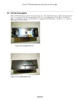
Figure 1 Fan Assembly: Top View................................................................................................................................................ 10
Figure 2 Fan Assembly: Bottom View .......................................................................................................................................... 10
Figure 3 Fan Assembly: Front View.............................................................................................................................................. 11
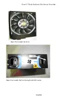
Figure 4 Fan Assembly: Top View Showing Identify LED Location.............................................................................................. 11
Figure 5 DE Enclosure VPD Label................................................................................................................................................ 12
Figure 6 Disk Enclosure HEX Cage ID ......................................................................................................................................... 17
Figure 7 Frame Photo showing UEPO location.............................................................................................................................. 18
Figure 8 UEPO assembly showing frame Identify Amber LED...................................................................................................... 19
Figure 9 Door Latch ..................................................................................................................................................................... 20
Figure 10 Door Latch handle shown extended ............................................................................................................................... 20
Figure 11 The Front Enclosure ID LED is located on the DE DCCAs............................................................................................ 21
Figure 12 Rear Enclosure ID LED is located on the bottom right side of the DE .......................................................................... 22
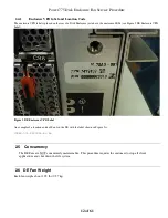
Figure 13 T1 and T4 Input Power LEDs on the DE DCCAs.......................................................................................................... 24
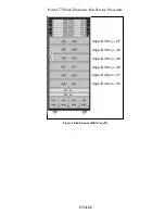
Figure 14: Disk Enclosure and UEPO Location Info..................................................................................................................... 25
Figure 15: Frame UEPO Service Position..................................................................................................................................... 26
Figure 16: DCCA Service Network Communications (E/NET) Cable ........................................................................................... 27
Figure 17 DE cabling.................................................................................................................................................................... 28
Figure 18 Disk Enclosure DCCA Power Cables (HPIC) ................................................................................................................ 29
Figure 19: Disk Enclosure Port Card Cabling ............................................................................................................................... 30
Figure 20 Photo of Front Rail Block Captive Screw ...................................................................................................................... 31
Figure 21: Front Rail Block Screws.............................................................................................................................................. 32
Figure 22 Water Hose Connector .................................................................................................................................................. 33
Figure 23: Disk Enclosure Rear Rail Block Captive Screws.......................................................................................................... 34
Figure 24 Cam Follower Storage Location Drawing ..................................................................................................................... 36
Figure 25 Cam Follower Drawing – in storage location at EIA 5 – zoomed in............................................................................... 37
Figure 26 Cam Followers Picture......................................................................................................................................... 38
Figure 27 Left Cam Follower
Figure 28 Right Cam Follower ............................................................................................... 38
Figure 29 Cam Follower engaged in Disk Enclosure channels .................................................................................................... 39
Figure 30 Blue-purple Recessed Touch Points............................................................................................................................... 41
Figure 31 Photo of Disk Enclosure in service position .................................................................................................................. 41
Figure 32 DE Extraction distance (edge of frame to tip of cable tray)............................................................................................ 42
Figure
33
Extender cables attached to DCCA1 ............................................................................................................................ 43
Figure 34 ¼ turn fastener fan cover removal................................................................................................................................. 44
Figure 35
Fan failure ID LED ................................................................................................................................................. 47
Figure 36 Fan removal rings ......................................................................................................................................................... 48
Figure 37 Lift fan out of disk enclosure......................................................................................................................................... 48
Figure 38 Fan blind mate connector ............................................................................................................................................. 49
Figure 39 T1 and T4 Input Power LEDs on the DE DCCAs.......................................................................................................... 52
Figure 40 Reinstall cover .............................................................................................................................................................. 53
Figure 41 Cam Follower locating pin ........................................................................................................................................... 54
Figure 42: Rail Block Rail Block Interfering with Drive Carrier ................................................................................................... 56
Figure 43: Rail Block Correctly Installed ..................................................................................................................................... 56
Table List
Table 1 Release / Revision History.................................................................................................................................................. 4
Table 2 Required Documents.......................................................................................................................................................... 4
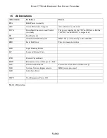
Table 3 Abbreviations..................................................................................................................................................................... 5
Table 4 Format for BPC command to blink a DE Fan ID LED...................................................................................................... 46
Table 5 Format for BPC command to turn off a DE Fan ID LED. ................................................................................................. 50