background image

Power775 Disk Enclosure Fan Service Procedure   


9 of 61 


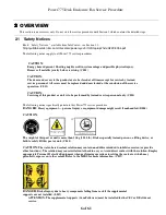
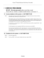
2.2  ATTENTION: File System Risk Statement 

 
The Global Parallel File System (GPFS) implementation of software RAID stripes data across all the Disk Enclosures in the 
cluster.  

If a single Disk Enclosure is powered off while GPFS is active, the file system will go into panic and become 

unavailable.   
 

This service procedure requires powering off a Disk Enclosure and because of this requires interaction with GPFS in order 
to limit impact to performance. 
 

2.3  Confirm how you got to this Power 775 DE Fan Service Procedure 

You should be performing this procedure if you have determined a Disk Enclosure Fan has failed and needs replacement. 
 
You should have downloaded this procedure from: 
 
InfoCenter Website:  

http://publib.boulder.ibm.com/infocenter/powersys/v3r1m5/topic/p7ee2/p7ee2kickoff.htm


This is the only valid source for the latest Power775 DE Fan Service Procedure 

Summary of Contents for Power 775

Page 1: ...Power775 Disk Enclosure Fan Service Procedure 1 of 61 Power775 Disk Enclosure Fan Service Procedure Last Modified 11 03 2011...

Page 2: ...ESS SHUTDOWN OF FILE SYSTEM CUSTOMER TASK 15 3 2 SHUTDOWN THE FILE SYSTEM CUSTOMER TASK 15 3 3 IDENTIFY THE FRAME SSR TASK 16 3 4 POWER OFF THE DISK ENCLOSURE CUSTOMER TASK 23 3 5 CONFIRM THAT 350V IS...

Page 3: ...ews 32 Figure 22 Water Hose Connector 33 Figure 23 Disk Enclosure Rear Rail Block Captive Screws 34 Figure 24 Cam Follower Storage Location Drawing 36 Figure 25 Cam Follower Drawing in storage locatio...

Page 4: ...C removing and replacing parts Under Disk Enclosure click Disk Enclosure Fan to download PDF p775_de_fan pdf This is the only valid source for the latest Power775 Disk Enclosure Fan Service Procedure...

Page 5: ...EC DCCA and DE DCCA respectively DE Disk Enclosure GPFS Global Parallel File System IBM s file system utilizing software RAID HDD Hard Disk Drive This also means hard drive LED Light Emitting Diode LI...

Page 6: ...s to be performed by trained service personnel only C032 The following notices specifically pertain to this Power775 service procedure DANGER Heavy equipment personal injury or equipment damage might...

Page 7: ...s voltage present Voltages present constitute a shock hazard which can cause severe injury or death L004 CAUTION Sharp edges corners or joints nearby L006 CAUTION Hazardous moving parts nearby L008 CA...

Page 8: ...istant gloves are needed for this procedure L014 DANGER Risk of electric shock due to water or a water solution which is present in this product Avoid working on or near energized equipment with wet h...

Page 9: ...e procedure requires powering off a Disk Enclosure and because of this requires interaction with GPFS in order to limit impact to performance 2 3 Confirm how you got to this Power 775 DE Fan Service P...

Page 10: ...capable of running with only 8 fans a service request will not be scheduled until at least 2 or 3 fans fail depending on the location of the failed fans When 2 or more fans fail the fan speed will in...

Page 11: ...Power775 Disk Enclosure Fan Service Procedure 11 of 61 Figure 3 Fan Assembly Front View Figure 4 Fan Assembly Top View Showing Identify LED Location...

Page 12: ...see Figure 5 DE Enclosure VPD Label Figure 5 DE Enclosure VPD Label An example of a location code of Fan 4 in the DE with the label shown in Figure 5 is U78AD 001 992001B P1 A4 2 5 Concurrency The DE...

Page 13: ...location 5 Hand Tool Kit P N 74Y0988 Torque Clutch P N 74Y0985 shipped in the Hand Tool Kit Ratchet handle P N 6428240 shipped in the Hand Tool Kit Extension 18 P N 46K2707 shipped in the Hand Tool Ki...

Page 14: ...E SSR TASK 16 3 4 POWER OFF THE DISK ENCLOSURE CUSTOMER TASK 23 3 5 CONFIRM THAT 350V IS OFF TO THE DISK ENCLOSURE SSR TASK 23 3 6 MOVE UEPO PANEL SSR TASK 25 3 7 DISCONNECT CABLES HOSES AND RETENTION...

Page 15: ...ng it down and leave the file system active for this procedure it is assumed impractical due to the excessive time required to move all the data For more details see related document GPFS Native RAID...

Page 16: ...acement by using the following command from the BPC Command Line This is the command syntax bpccmd c 27 blank 0000 cage ID FRU ID LED blink state 00 off 02 blink blank 11 cage ID see Figure 6 FRU ID 0...

Page 17: ...Power775 Disk Enclosure Fan Service Procedure 17 of 61 Figure 6 Disk Enclosure HEX Cage ID Cage ID Hex 0F Cage ID Hex 0D Cage ID Hex 0B Cage ID Hex 09 Cage ID Hex 07 Cage ID Hex 05...

Page 18: ...STEP 6 Locate the frame Confirm that it is the correct frame by checking that its UEPO Panel Identify LED is blinking This LED is located on the UEPO panel and it is marked by the symbol see Figure 7...

Page 19: ...ors DANGER Hazardous voltage present Voltages present constitute a shock hazard which can cause severe injury or death L004 Locate the latch along the left side of the door push in on the X button the...

Page 20: ...Power775 Disk Enclosure Fan Service Procedure 20 of 61 Figure 9 Door Latch Figure 10 Door Latch handle shown extended...

Page 21: ...Lift Tool Kit STEP 9 Identify the Disk Enclosure Identify the Disk Enclosure with the failed fans by looking for the blinking amber Enclosure ID LEDs on the DE DCCAs on the front side of the Disk Encl...

Page 22: ...llowing command from the BPC FSP Command Line This is the command syntax bpccmd c 27 blank 0000 cage ID FRU ID LED blink state 00 off 02 blink blank 11 cage ID see table below FRU ID 01 for the DE Ide...

Page 23: ...do not receive this contact the next level of support ATTENTION Be very careful that you are in the correct frame and that you type this command exactly as it will power off the cage you type If you a...

Page 24: ...Power775 Disk Enclosure Fan Service Procedure 24 of 61 Figure 13 T1 and T4 Input Power LEDs on the DE DCCAs...

Page 25: ...19 Figure 14 Disk Enclosure and UEPO Location Info STEP 15 DO NOT disconnect the UEPO cables and DO NOT put the UEPO switch in the OFF position Loosen the blue colored thumb screw located at the botto...

Page 26: ...Service Procedure 26 of 61 STEP 17 Place the UEPO in the Frame UEPO Service Position in the Rack see Figure 15 Figure 15 Frame UEPO Service Position STEP 18 Hand tighten the UEPO blue thumb screw to...

Page 27: ...ble Assembly E NET test tool P N 45D8000 shipped in Power 775 Fill Drain Tool Kit If the test tool is not labelled follow the E NET cable to the other end and label it T2 Do not connect it to the DCCA...

Page 28: ...Power775 Disk Enclosure Fan Service Procedure 28 of 61 Figure 17 DE cabling...

Page 29: ...beled label them now Find the cable that was connected to and labeled DCCA1 T1 Connect this cable to Cable Assembly HPIC tool P N 45D7998 shipped in Power 775 Fill Drain Tool Kit using 0 07Nm torque I...

Page 30: ...se cables are not labeled label them now Disconnect these cables from the DE There will be up to 32 such cables see Figure 19 You may have to remove some of the velcro ties in order to disconnect the...

Page 31: ...STEP 23 Determine if the Front Rail Blocks will interfere with any cables which will damage the cables If you are sure they will not interfere you can leave them attached If they will interfere with a...

Page 32: ...Power775 Disk Enclosure Fan Service Procedure 32 of 61 Figure 21 Front Rail Block Screws...

Page 33: ...Protective Equipment when performing operations involving the coolant or which may potentially expose you to the coolant Refer to the MSDS for more information C037 CAUTION Protective eyewear is neede...

Page 34: ...left side and one on the right side of the DE which hold the Rear Rail Block to the Rack Slide Rails see Figure 23 Loosen these screws using the 5mm Hex Torque Tool PN 74Y0986 shipped in the Hand Too...

Page 35: ...ATTENTION The supplemental supports Cam Followers must be installed for the CEC or DE slide out service In order to do this unscrew the shipping screws of the left and right cam followers see Figure 2...

Page 36: ...Power775 Disk Enclosure Fan Service Procedure 36 of 61 Figure 24 Cam Follower Storage Location Drawing...

Page 37: ...Power775 Disk Enclosure Fan Service Procedure 37 of 61 Figure 25 Cam Follower Drawing in storage location at EIA 5 zoomed in...

Page 38: ...Power775 Disk Enclosure Fan Service Procedure 38 of 61 Figure 26 Cam Followers Picture Figure 27 Left Cam Follower Figure 28 Right Cam Follower...

Page 39: ...Power775 Disk Enclosure Fan Service Procedure 39 of 61 Figure 29 Cam Follower engaged in Disk Enclosure channels Left Cage Channel Left Cage Channel Cam Follower Rollers...

Page 40: ...ice CAUTION Do not pull out more than one drawer at a time The rack might become unstable if you pull out more than one drawer at a time L024 Check carefully that all cables are out of the way of the...

Page 41: ...Power775 Disk Enclosure Fan Service Procedure 41 of 61 Figure 30 Blue purple Recessed Touch Points Figure 31 Photo of Disk Enclosure in service position...

Page 42: ...Power775 Disk Enclosure Fan Service Procedure 42 of 61 Figure 32 DE Extraction distance edge of frame to tip of cable tray...

Page 43: ...sing the 2mm Hex Torque Driver P N 74Y0983 with a torque of 0 07Nm Care must be taken to insure that the cables are connected correctly The HPIC extension tool must connect HPIC cable DCCA1 T1 to DE D...

Page 44: ...er to Figure 29 Locate the fan cover and the three turn fasteners Lift the handle on the turn fasteners and rotate them turn counterclockwise Lift the fan cover off the box For this operation it may b...

Page 45: ...lect DCCA1 Type in the following inserting the correct Cage ID for the DE you are servicing bpccmd c 11110002xx90 Where xx is the Cage ID of the DE you are servicing This field will be 05 07 09 0B 0D...

Page 46: ...r 0F see Figure 6 yy is the FRU ID Choose this based on the FAN position column in Table 5 The correct return code is 001100 If you do not receive this contact the next level of support FAN position E...

Page 47: ...uld be blinking showing which fans are to be replaced see Figure 30 Confirm also the A1 A12 location labels against the location codes of the failed fans For the this and the next several STEPs it may...

Page 48: ...e the fans by pulling the retention rings toward each other and lifting the fan out of the DE see Figure 36 and Figure 37 CAUTION Hazardous moving parts nearby L008 Figure 36 Fan removal rings Figure...

Page 49: ...o each open slot see Figure 38 When fully seated the fan will be latched into the Disk Enclosure Pull up on one fan ring to check if the fan is fully seated Never force the fan down If the fan is not...

Page 50: ...FRU ID 02 BLINK 00 OFF FAN1 A1 bpccmd c 27110000xxB000 B0 00 FAN2 A2 bpccmd c 27110000xxB100 B1 00 FAN3 A3 bpccmd c 27110000xxB200 B2 00 FAN4 A4 bpccmd c 27110000xxB300 B3 00 FAN5 A5 bpccmd c 2711000...

Page 51: ...wer off the cage you type If you are off by just one digit you can easily power off a CEC or DE in another cage of the frame 3 10 Slide Disk Enclosure back into the frame SSR TASK STEP 37 Confirm that...

Page 52: ...Power775 Disk Enclosure Fan Service Procedure 52 of 61 Figure 39 T1 and T4 Input Power LEDs on the DE DCCAs...

Page 53: ...extension assembly from DCCA1 Disconnect the E NET extension assembly from DCCA1 STEP 39 Replace fan cover see Figure 35 With cover oriented vertically insert tabs into chasses and rotate cover to th...

Page 54: ...the locating pin out of the frame and lifting the Cam Follower see figure 36 Return the Cam Followers to the original storage location at the lowest position of the frame near EIA 5 Screw the shippin...

Page 55: ...cable end should have two labels The label closest to the connector between the SN label and the connector tells you the location to plug that end The label on the other side of the SN label tells you...

Page 56: ...all them using the Front Rail Block hex screws see Figure 21 NOTE Make sure the Rail Blocks will not interfere with removal of the adjacent Drive Carriers Figure 42 Rail Block Rail Block Interfering w...

Page 57: ...ched to the DE from the Operating Systems owning the DE now before the DE is turned back on so that there is not time wasted in spinning down the drives If you are running Linux no action is necessary...

Page 58: ...support STEP 56 From the BPC FSP command line make sure all the fans are functional with the following command bpccmd b f If a fan is not functional use Power775 Disk Enclosure Fan Service Procedure...

Page 59: ...FSP Command Line 1 The HMC can be accessed via the keyboard display that resides in the network management rack 2 Login to the HMC if not done already 3 In the HMC navigation pane expand Systems Mana...

Page 60: ...ame IP Address then click the OK button 6 The ASM login window is presented Acquire the necessary User ID and Password celogin requires Daily PW from the IBM Support Center celogin1 might be has enabl...

Page 61: ...8 The ASM BPC FSP Command line will be presented Enter the commands defined in the paper service procedures at this command line and press the Enter key or click the Execute button 9 Return to the st...

Reviews: