Power 775 D-Link Service Procedure
PN: 41U8487, EC N44172
8 of 27
2.3
D-Link Description
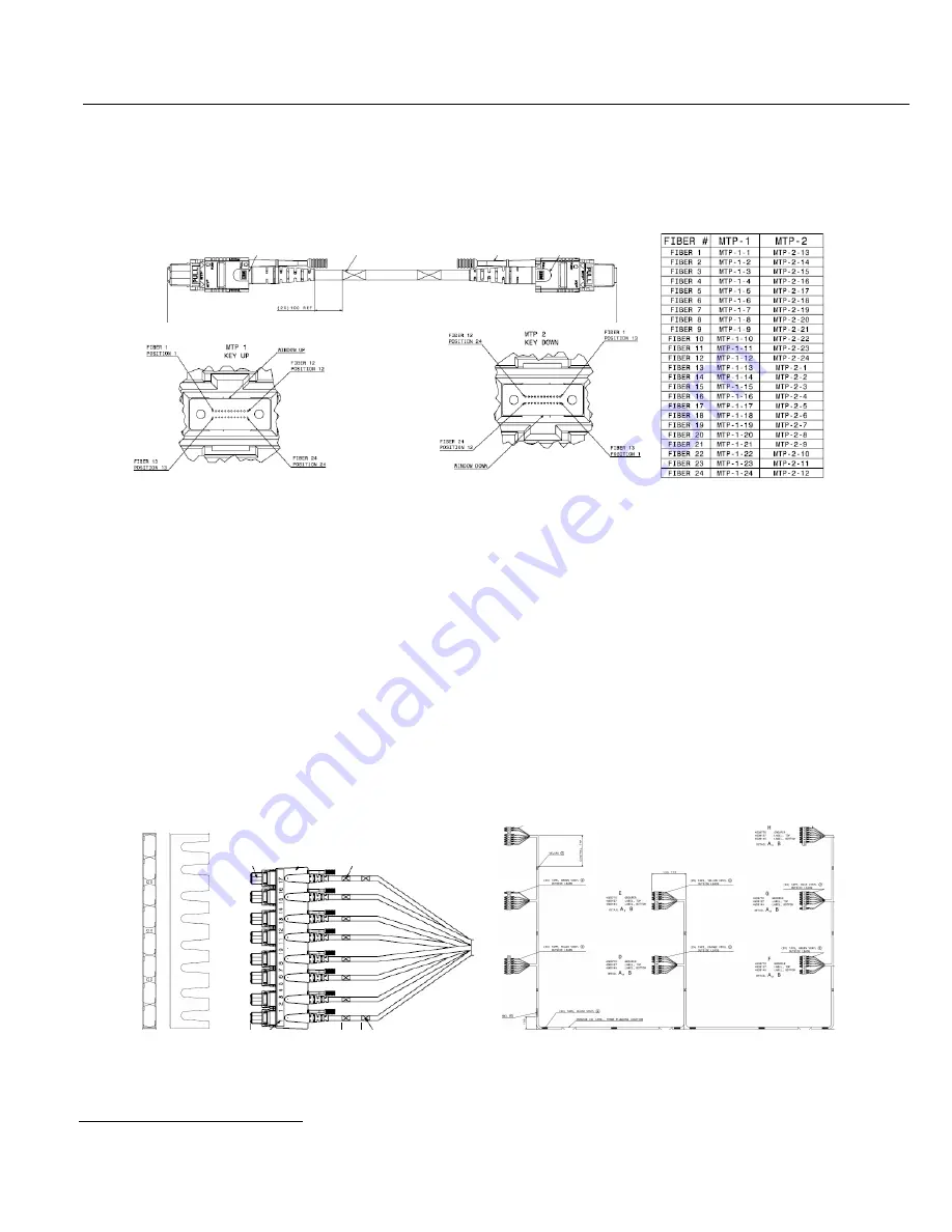
The D-Links that interconnect SuperNodes to each other consist of 24-fiber cables, with an orange PVC
jacket. Each cable is 3.8mm in diameter. Each end of the cable has an MTP-brand 24-fiber MPO connector,
with an attached push/pull tab that allows actuation of connectors in tightly-packed arrays.
The fibers in the top row of the left-hand, key-up connector of this figure are connected directly across to the
top row of fibers in the right-hand, key-down connector, and vice versa. When cables are plugged into system
adapter ports, they are always oriented with keys up on both ends, so the cable does a half-circle turn or helix
half-twist, and the top row in each adapter port is wired to the bottom row at the other end of the cable.
1
Removing or inserting an individual D-Link from the CEC drawer can be done by pulling or pushing,
respectively, on its push/pull tab. Insertion can also be done by pushing on the connector’s strain relief boot.
In most system installations, D-Links are gathered into Cable Assemblies, or “wiring harness” bundles, which
consist of a reasonably large number of cables (14-150 or more), with vinyl tape or hook-and-loop tape
wrapped around them, and connector groupers used to gather together a row of up to 8 connectors. The
specific design of each assembly (number of D-Link cables, organization of connectors into groupers, etc.)
depends on the size and scale of the system, and on the number of CEC drawers that are interconnected and is
described in the system-specific System Installation Guide.
1
Note that this over-and-under orientation of transmitting and receiving rows is different than many one-row connectors (e.g., RJ-
45, or QSFP), where transmitting and receiving lanes are left-and-right of each other. With a two-row connector,
Grouper
8 MTP connectors with
push/pull tabs in a grouper
Example Cable Bundle Assembly


