4.
If applicable, replace the front cover. For instructions to replace the front cover on an expanded
function system, see “Installing the front cover on a rack-mounted 5148-21L, 5148-22L, 8247-21L,
8247-22L, 8284-21A, or 8284-22A system” on page 153.
5.
Return to the console and wait until the Concurrent Maintenance Results display is shown, and then
press
Enter
.
6.
If you return to the Service Action Log display, exit the service action log.
7.
When the Hardware Service Manager (HSM) display is shown, press F3.
8.
To configure the newly installed disk drive or solid-state drive, see “Configuring a disk drive or
solid-state drive for use in an IBM i system or IBM i logical partition” on page 115.
9.
To rebuild the data on the replacement disk drive or solid-state drive, see “Rebuilding data on a
replacement disk drive or solid-state drive in a system or logical partition running the IBM i
operating system” on page 120.
Removing and replacing a disk drive or solid-state drive by using the
hot-spare function in the 8284-21A or 8284-22A system with the power
turned on in IBM i
Learn how to remove and replace a disk drive or solid-state drive (SSD) by using the hot-spare function
in a system with the IBM i operating system or an IBM i logical partition that controls the drive location
powered on.
To remove and replace a disk drive or solid-state drive in a system, complete the following steps:
1.
2.
3.
A
P8HAL517-2
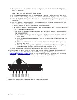
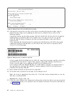
Figure 69. Covering the SSD cage in an expanded function system
Disk drives or solid-state drives
71
Summary of Contents for Power System 5148-21L
Page 2: ......
Page 18: ...xvi Disk drives or solid state drives ...
Page 202: ...184 Disk drives or solid state drives ...
Page 203: ......
Page 204: ...IBM ...


