d.
Verify that the disk drive or solid-state drive that you installed is shown on this display.
2.
Ensure that you have the electrostatic discharge (ESD) wrist strap on and that the ESD clip is
connected to an unpainted metal surface. If not, do so now.
3.
If you replaced a drive and have not verified the drive yet, verify that the power LED is ON (green)
and the amber fault LED is OFF (not lit) for the replaced drive on the front of the system.
4.
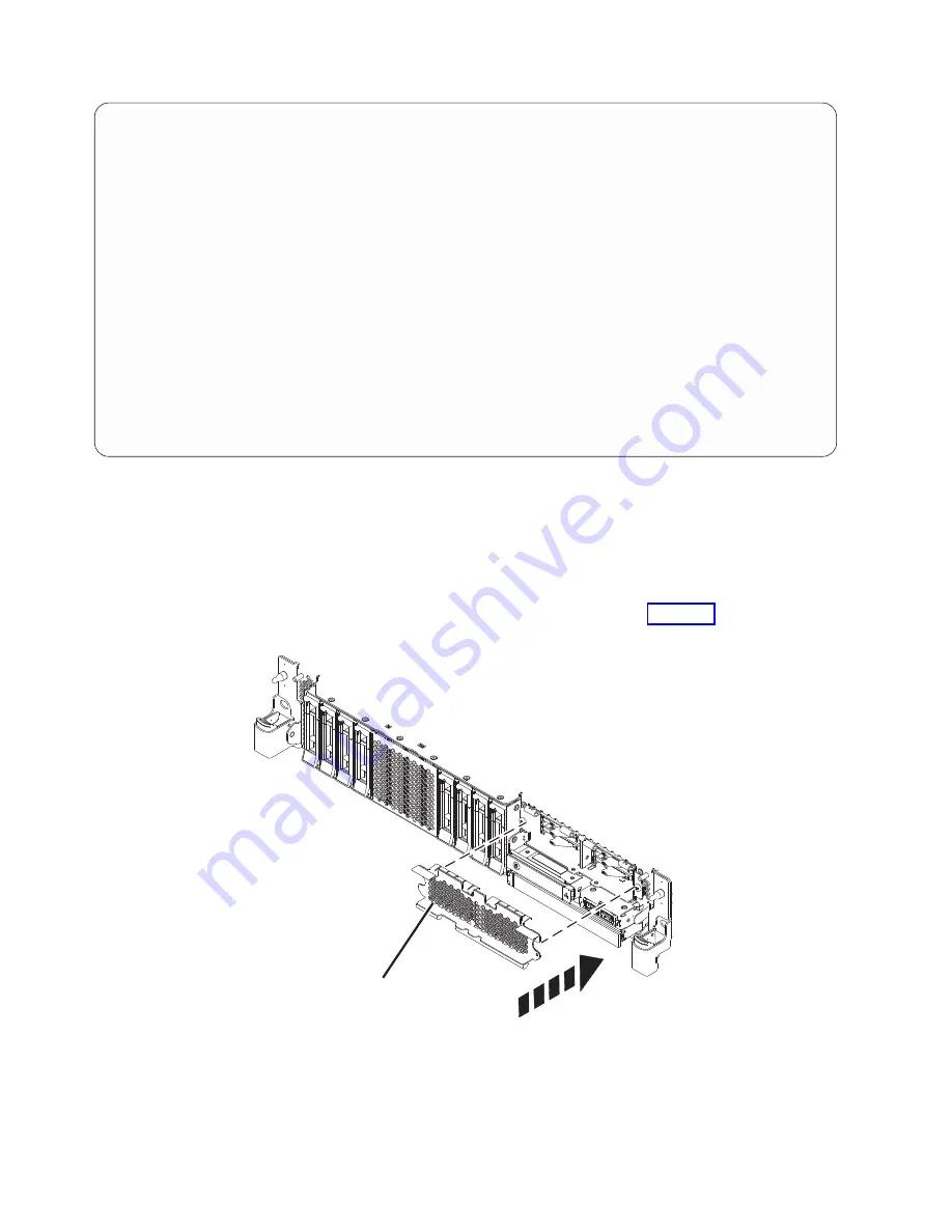
If applicable, cover the SSD cage with the perforated plate (A) as shown in Figure 99.
Display Hardware Status
Type option, press Enter.
1=Display hardware resource information details
OPT Name
PCI/SCSI Location
Description
Status
--- ------ -------------------------- ------------------------- ----------------
0000:01:00.0/0:
PCI-E SAS RAID Adapter
Operational
0000:01:00.0/0:0:0:0
Advanced Function SSD
Active
0000:01:00.0/0:0:1:0
Advanced Function SSD
Active
0000:01:00.0/0:0:2:0
Advanced Function SSD
Active
0000:01:00.0/0:0:3:0
Advanced Function SSD
Active
0000:01:00.0/0:0:4:0
Advanced Function SSD
Active
0000:01:00.0/0:0:5:0
Advanced Function SSD
Active
0000:01:00.0/0:0:6:0
Advanced Function SSD
Active
0000:01:00.0/0:0:8:0
Enclosure
Active
0000:01:00.0/0:0:9:0
Enclosure
Active
0001:01:00.0/1:
PCI-E SAS RAID Adapter
Operational
0001:01:00.0/1:0:3:0
Advanced Function SSD
Remote
0001:01:00.0/1:0:4:0
Advanced Function SSD
Remote
0001:01:00.0/1:0:5:0
Advanced Function SSD
Remote
More...
e=Exit
q=Cancel
r=Refresh
t=Toggle
f=PageDn
b=PageUp
Figure 98. Example Display Hardware Status
A
P8HAL517-2
Figure 99. Covering the SSD cage in an expanded function system
96
Disk drives or solid-state drives
Summary of Contents for Power System 5148-21L
Page 2: ......
Page 18: ...xvi Disk drives or solid state drives ...
Page 202: ...184 Disk drives or solid state drives ...
Page 203: ......
Page 204: ...IBM ...


