11.
If you are replacing more than one drive, repeat the steps in this procedure until all drives are
replaced.
12.
Proceed to the procedure for preparing the system for operation. For instructions, see “Preparing the
8284-21A or 8284-22A system for operation after removing and replacing a drive with the power
turned on in IBM i” on page 70.
13.
To replace an SSD in an expanded function system, continue with the next step.
14.
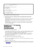
Return to the console and complete the following steps. Wait until the Concurrent Maintenance
Results display is shown.
a.
Press
F12
.
b.
The physical locations that you entered while you removed the disk drive or solid-state drive
might still show on the display. If not, retype the physical location where you want to install the
new disk drive or solid-state drive.
v
In the example,
U787A.001.1234567-P3-D4
, you would install a disk drive in the system unit
with type 9406, Model 520, sequence number 1234567, and disk drive or solid-state drive
position P3–D4.
v
In the example,
U5074.001.1234567-DB3-D32
, you would install a disk drive or solid-state drive
in the expansion unit with type 5074, model 001, sequence number 1234567, and disk drive or
solid-state drive position DB3–D32.
c.
Select
2
(Install device) for the Action to be completed.
d.
Set the time delay. For example, for one minute:
01
.
Note:
You can set an appropriate time delay of 01 - 19 minutes to allow adequate time to access
the disk drive or solid-state drive.
Important:
Do not press
Enter
yet.
15.
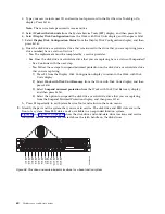
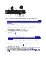
With the SSD drive bay handle (A) in the unlocked position, pull the lever outward to gain access to
the guide rails in the SSD slot. Support the bottom of the SSD as you align it with the guide rails in
the SSD slot. See Figure 68 on page 70.
Note:
Support the drive by holding the drive by its sides.
16.
Slide the drive halfway into the system.
17.
In the HSM display, select the drive that you want to install or replace.
18.
Press
Enter
on the console.
Important:
When you press
Enter
, after your selected time delay, the service indicator light comes
on (solid) for 18 seconds. You then have 18 seconds to slide the drive all the way in and then lock it
in place by pushing in the drive handle. You can set an appropriate time delay of 01 - 19 minutes to
allow adequate time to access the disk drive or solid-state drive.
19.
When the identify LED turns on solid, slide the drive all the way into the system until the drive
stops.
20.
Lock the drive by rotating the bay handle (A) in the direction that is shown in Figure 68 on page 70.
Important:
When you install an SSD, ensure that the SSD is fully seated and is all the way into the
system.
Disk drives or solid-state drives
69
Summary of Contents for Power System 5148-21L
Page 2: ......
Page 18: ...xvi Disk drives or solid state drives ...
Page 202: ...184 Disk drives or solid state drives ...
Page 203: ......
Page 204: ...IBM ...


