background image

v

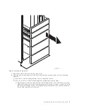
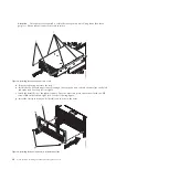
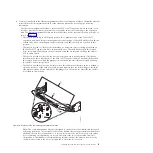
The rail installation can be completed by one person. However, the installation is easier if one
person is positioned at the front of the rack and one person is positioned at the rear of the rack.

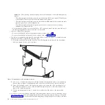
d.

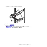
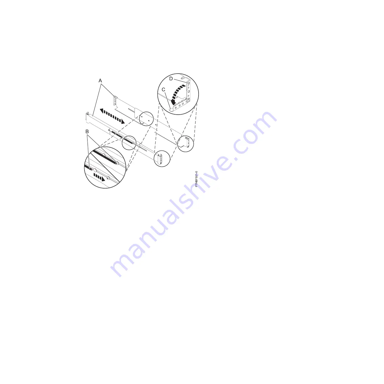
Extend the left rail and insert the rail pins

(D)

into the two lowest mounting holes marked on the

rack. Rotate up the front clamp

(C)

to secure the rail in place.

e.

Move to the rear of the rack, extend the right rail, and insert the rail pins

(D)

into the two lowest

mounting holes marked on the rack. Rotate up the back clamp

(C)

to secure the rail in place.

f.

Extend the left rail and insert the rail pins

(D)

into the two lowest mounting holes marked on the

rack. Rotate up the back clamp

(C)

to secure the rail in place.

g.

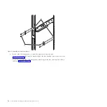
At the rear of the rack, use two M5 screws

(E)

, one below each rail pin

(D)

, to secure the left rail

to the back of the rack.

h.

Use two M5 screws

(E)

, one below each rail pin

(D)

, to secure the right rail to the back of the rack.

i.

Move to the front of the rack. Use one M5 screw

(E)

below the top rail pin to secure the left rail to

the front of the rack.

Figure 4. Installing the rails

Installing the 5802 and 5877 expansion units: Details

7

Summary of Contents for Power System 5802

Page 1: ...Power Systems Installing the 5802 and 5877 expansion units GI11 4307 09...

Page 2: ......

Page 3: ...Power Systems Installing the 5802 and 5877 expansion units GI11 4307 09...

Page 4: ...Notices manual G229 9054 and the IBM Environmental Notices and User Guide Z125 5823 This edition applies to IBM Power Systems servers that contain the POWER7 processor and to all associated models Cop...

Page 5: ...32 Model 8231 E2C connector locations 32 Model 8231 E2D connector locations 33 Model 8233 E8B connector locations 34 Model 8246 L1S connector locations 35 Model 8246 L2S connector locations 35 Model...

Page 6: ...iv Power Systems Installing the 5802 and 5877 expansion units...

Page 7: ...ct The documentation contains the safety information in your national language with references to the U S English source Before using a U S English publication to install operate or service this produ...

Page 8: ...at will be attached to this product to properly wired outlets v When possible use one hand only to connect or disconnect signal cables v Never turn on any equipment when there is evidence of fire wate...

Page 9: ...e customer to ensure that the outlet is correctly wired and grounded to prevent an electrical shock CAUTION v Do not install a unit in a rack where the internal rack ambient temperatures will exceed t...

Page 10: ...upport the weight of the loaded rack cabinet Refer to the documentation that comes with your rack cabinet for the weight of a loaded rack cabinet v Verify that all door openings are at least 760 x 230...

Page 11: ...This product might contain one or more of the following devices CD ROM drive DVD ROM drive DVD RAM drive or laser module which are Class 1 laser products Note the following information v Do not remove...

Page 12: ...bling information for NEBS Network Equipment Building System GR 1089 CORE The following comments apply to the IBM servers that have been designated as conforming to NEBS Network Equipment Building Sys...

Page 13: ...that you received all of the parts that you ordered Each order contains at a minimum the following items v Left and right rack mounting rails v Mounting screws v Power supply cables If your shipment...

Page 14: ...g template see step 5d2 on page 5 Install the rail assembly in the rack To install the mounting hardware in the rack see step 6 on page 6 Install the expansion unit on the rail assembly To install the...

Page 15: ...5877 expansion unit was delivered separately from a rack and you must mount the enclosure in an existing rack and complete the installation Note If the rack is not yet installed you must first comple...

Page 16: ...t into the rack as follows a Determine where in the rack to place the expansion unit in relation to other system hardware As you plan keep the following steps in mind 1 Organize larger and heavier uni...

Page 17: ...ack mounting template complete the following steps a Face the front of the rack and work from the left side Make a note of both the lowest and highest EIA units to be used for the expansion unit Use t...

Page 18: ...e marks on the corresponding mounting holes on the rear right side of the rack 6 Install the rail assembly into the rack as follows Important To complete this procedure use two people to attach the ra...

Page 19: ...holes marked on the rack Rotate up the back clamp C to secure the rail in place f Extend the left rail and insert the rail pins D into the two lowest mounting holes marked on the rack Rotate up the b...

Page 20: ...marks made previously on the rear EIA strips Each side contains three marks Insert a nut clip these six locations 7 Install the expansion unit onto the rails as follows a Remove the four thumb screws...

Page 21: ...e touch points on each side of the expansion unit pull the bezel straight out to remove the bezel from the front of the expansion unit 4 Remove the two nut clips that were used to secure the bezel to...

Page 22: ...nut clips on the left and right rails See the previous figure f Install the bezel L onto the expansion unit Press the bezel into place and secure it with two M5 screws M on the left and right rails S...

Page 23: ...position The shelf is rotated down to the the next lower position 3 to permit service of hardware installed in the space directly above the 5802 or 5877 expansion unit The shelf side brackets A conta...

Page 24: ...To assemble the cable management bracket complete the following steps 1 Locate the center shelf section B shown in the following figure and identify the attachment hole that appears at each end of the...

Page 25: ...tall retention brackets A on the left and right rack flanges as shown in Figure 13 on page 14 Attach each bracket by applying M5 screws B to the two locations directly above the rail clamp where nut c...

Page 26: ...ention brackets apply the four securing screws A as shown in Figure 14 on page 15 v If you have installed the cable management bracket apply the four securing screws B as shown in Figure 14 on page 15...

Page 27: ...before connecting and configuring the hardware in your configuration a Review the following connector locations figure for the 5802 and 5877 Figure 14 Applying the securing screws Installing the 5802...

Page 28: ...drive partitions switch is located at the rear of the 5802 expansion unit just below the SAS connectors v If the hard disk drive partitions switch position is changed you must power the 5802 expansion...

Page 29: ...dapters PCIe Dual x4 3 Gb SAS RAID v Two FC ESA1 adapters PCIe2 RAID SAS Dual port 6 Gb v Two FC 5913 adapters PCIe2 1 8 GB cache RAID SAS Tri port 6 Gb Note The top ports of the FC 5913 pair must att...

Page 30: ...ensure that you have the minimum number of available disks for each RAID level RAID 0 Minimum of one drive per array RAID 5 Minimum of three drives per array RAID 6 Minimum of four drives per array R...

Page 31: ...a configuration that includes two hard disk drive partitions nine disks per hard disk drive partition a dual SAS adapter pair per hard disk drive partition that controls the disks in the partition and...

Page 32: ...n HD SAS AA cable 3 Attach an AT cable B from the same numbered port on each SAS adapter A of a dual SAS adapter pair to SAS connectors 1 and 2 on the 5802 SAS conduit card C as shown in the following...

Page 33: ...h is located at the rear of the 5802 expansion unit just below the SAS connectors 2 Choose one of the following SAS adapter and cable combination options v One FC ESA1 adapter PCIe2 RAID SAS Dual port...

Page 34: ...87 disk drive enclosure by using SAS YO cables D 6 Go to step 1i on page 25 f Complete the following steps to cable a configuration that includes two hard disk drive partitions nine disks per hard dis...

Page 35: ...onnectivity to all drives Note For the following operating systems this must be a RAID configuration AIX Linux 1 Set the hard disk drive partitions switch to position 1 The hard disk drive partitions...

Page 36: ...e hard disk drive partitions switch to position 4 The hard disk drive partitions switch is located at the rear of the 5802 expansion unit just below the SAS connectors 2 Choose one of the following SA...

Page 37: ...he expansion unit to the system by completing the following steps a Read important information about expansion units at Overview for I O expansion units http publib boulder ibm com infocenter systems...

Page 38: ...26 Power Systems Installing the 5802 and 5877 expansion units...

Page 39: ...Learn about 12X system power control network SPCN and PCIe connector locations Server connectors Learn about connector locations for servers Model 8202 E4B connector locations Learn about connector lo...

Page 40: ...12X DDR and PCIe cable ports The server contains a serial attached SCSI SAS port v Support for disk drive enclosures as shown in the following figure is as follows The server contains a SAS port v Su...

Page 41: ...ial attached SCSI SAS port v Support for disk drive enclosures as shown in the following figure is as follows The server contains a SAS port v Support for PCIe storage enclosures as shown in the follo...

Page 42: ...he following enclosures v Support for expansion units as shown in the following figure is as follows The card installed in the C1 slot can contain two 12X double data rate DDR cable ports However the...

Page 43: ...following enclosures v Support for expansion units as shown in the following figure is as follows The card installed in the C1 slot can contain two 12X double data rate DDR cable ports However the C1...

Page 44: ...ing enclosures v Support for expansion units as shown in the following figure is as follows The C1 slot must contain the system power control network SPCN card and the C8 slot must contain the card wi...

Page 45: ...on units as shown in the following figure is as follows The C1 slot must contain the system power control network SPCN card and the C8 slot must contain the card with two 12X double data rate DDR cabl...

Page 46: ...e cable ports and 12X DDR cable ports at the same time The server contains a SAS port Model 8233 E8B connector locations Learn about connector locations on rack mounted models Figure 34 Model 8231 E2D...

Page 47: ...PCIe cable ports The card installed in the C3 slot can contain two 12X DDR cable ports However the C3 slot cannot provide both 12X DDR and PCIe cable ports v Support for disk drive enclosures as show...

Page 48: ...X DDR and PCIe cable ports v Support for disk drive enclosures as shown in the following figure is as follows The server contains a SAS port v Support for PCIe storage enclosures as shown in the follo...

Page 49: ...ocations Learn about connector locations Figure 40 Model 8412 EAD connector locations for expansion units disk drive enclosures and PCIe storage enclosures Figure 41 Model 9117 MMB or 9179 MHB connect...

Page 50: ...n the C3 slot can contain two 12X DDR cable ports However the C3 slot cannot provide both 12X DDR and PCIe cable ports v Support for disk drive enclosures as shown in the following figure is as follow...

Page 51: ...odel 5802 and 5877 connector locations Learn about connector locations Figure 43 Model 9117 MMD or 9179 MHD connector locations for expansion units disk drive enclosures and PCIe storage enclosures Fi...

Page 52: ...40 Power Systems Installing the 5802 and 5877 expansion units...

Page 53: ...or changes in the product s and or the program s described in this publication at any time without notice Any references in this information to websites not owned by the manufacturer are provided for...

Page 54: ...r updated information and fixes applicable to the system and related software Homologation statement This product may not be certified in your country for connection by any means whatsoever to interfa...

Page 55: ...areil num rique de la classe A est conforme la norme NMB 003 du Canada European Community Compliance Statement This product is in conformity with the protection requirements of EU Council Directive 20...

Page 56: ...eline with Modifications products greater than 20 A per phase Electromagnetic Interference EMI Statement People s Republic of China Declaration This is a Class A product In a domestic environment this...

Page 57: ...Erweiterungskomponenten von Fremdherstellern ohne Empfehlung von IBM gesteckt eingebaut werden EN 55022 Klasse A Ger te m ssen mit folgendem Warnhinweis versehen werden Warnung Dieses ist eine Einrich...

Page 58: ...inst harmful interference in a residential installation This equipment generates uses and can radiate radio frequency energy and if not installed and used in accordance with the instructions may cause...

Page 59: ...of EU Council Directive 2004 108 EC on the approximation of the laws of the Member States relating to electromagnetic compatibility IBM cannot accept responsibility for any failure to satisfy the pro...

Page 60: ...n Handb chern beschrieben zu installieren und zu betreiben Des Weiteren d rfen auch nur von der IBM empfohlene Kabel angeschlossen werden IBM bernimmt keine Verantwortung f r die Einhaltung der Schutz...

Page 61: ...cial Use You may reproduce distribute and display these publications solely within your enterprise provided that all proprietary notices are preserved You may not make derivative works of these public...

Page 62: ...50 Power Systems Installing the 5802 and 5877 expansion units...

Page 63: ......

Page 64: ...Part Number 00L5079 Printed in USA GI11 4307 09 1P P N 00L5079...

Reviews: