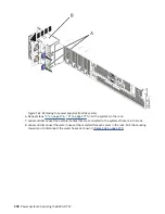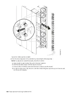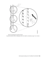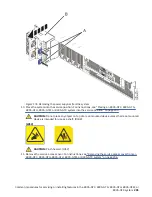
Figure 170. Connecting the hoses and opening the valves
4. Repeat step “3” on page 186 to connect the facility water return hose to the manifold hose.
Preparing the 8335-GTW or 8335-GTX system for operation after you remove and replace
the water manifold
To prepare the system for operation after removing and replacing a water manifold, complete the steps in
this procedure.
Procedure
1. Replace the rack rail on the side of the rack where the manifold is mounted.
2. Replace the system into the rack.
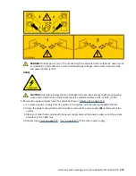
CAUTION: This system requires two people to replace the system into the rack.
If your rack has slider rails; replace the system on the rails. Place the system into the operating
position. For instructions, see “Placing an 8335-GTC, 8335-GTG, 8335-GTH, 8335-GTW, or 8335-
GTX system into the operating position” on page 211.
3. Using your labels, reconnect the external cables to the system.
4. Reconnect the water hoses at the rear of the rack, as shown in Figure 171 on page 188.
Removing and replacing parts in the 8335-GTW or 8335-GTX 187
Summary of Contents for Power System 8335-GTW
Page 1: ...Power Systems Servicing the 8335 GTW IBM...
Page 14: ...xiv Power Systems Servicing the 8335 GTW...
Page 204: ...190 Power Systems Servicing the 8335 GTW...
Page 234: ...220 Power Systems Servicing the 8335 GTW...
Page 245: ......
Page 246: ...IBM...

