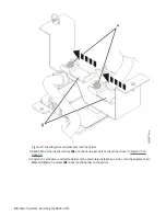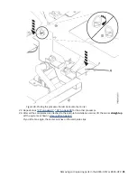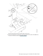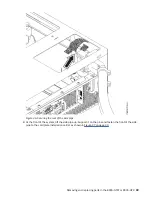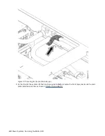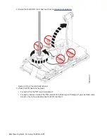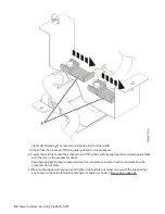
Figure 40. Placing the processor holder back onto the carrier
d) Repeat step “10” on page 41 for each cold plate.
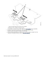
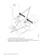
11. Attach the GPU cold plates to the holder.
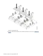
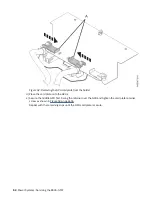
a) Insert the cold plate pins (A) into the holder as shown in Figure 41 on page 44.
Removing and replacing parts in the 8335-GTW or 8335-GTX 43
Summary of Contents for Power System 8335-GTW
Page 1: ...Power Systems Servicing the 8335 GTW IBM...
Page 14: ...xiv Power Systems Servicing the 8335 GTW...
Page 204: ...190 Power Systems Servicing the 8335 GTW...
Page 234: ...220 Power Systems Servicing the 8335 GTW...
Page 245: ......
Page 246: ...IBM...


