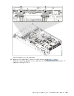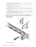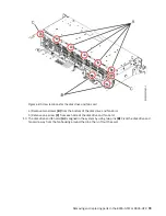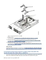
Figure 68. Screw locations for the disk drive and fan card
a) Remove two screws (B) from the bottom of the disk drive and fan card.
b) Remove one screw (C) from each side of the disk drive and fan card.
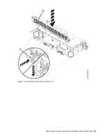
10. The disk drive and fan card (A) is aligned in the system by using two pins (B). Pivot the disk drive and
fan card away from the fan housing around the pins; then, lift out the card.
Removing and replacing parts in the 8335-GTW or 8335-GTX 73
Summary of Contents for Power System 8335-GTW
Page 1: ...Power Systems Servicing the 8335 GTW IBM...
Page 14: ...xiv Power Systems Servicing the 8335 GTW...
Page 204: ...190 Power Systems Servicing the 8335 GTW...
Page 234: ...220 Power Systems Servicing the 8335 GTW...
Page 245: ......
Page 246: ...IBM...

