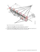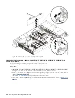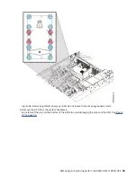
Figure 76. Location of the disk and fan signal cable and connectors
3. Release the cable from the retaining clip on the inside wall of the system.
4. Label and disconnect the disk and fan signal cable (A) from the disk drive and fan card (B) and from
the system backplane (C).
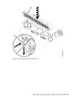
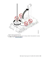
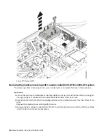
Using your thumb, press the release latch on the connector to remove a cable. See Figure 77 on page
83.
82 Power Systems: Servicing the 8335-GTW
Summary of Contents for Power System 8335-GTW
Page 1: ...Power Systems Servicing the 8335 GTW IBM...
Page 14: ...xiv Power Systems Servicing the 8335 GTW...
Page 204: ...190 Power Systems Servicing the 8335 GTW...
Page 234: ...220 Power Systems Servicing the 8335 GTW...
Page 245: ......
Page 246: ...IBM...


