background image

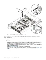
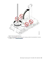
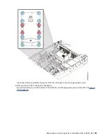
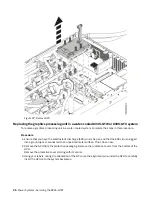
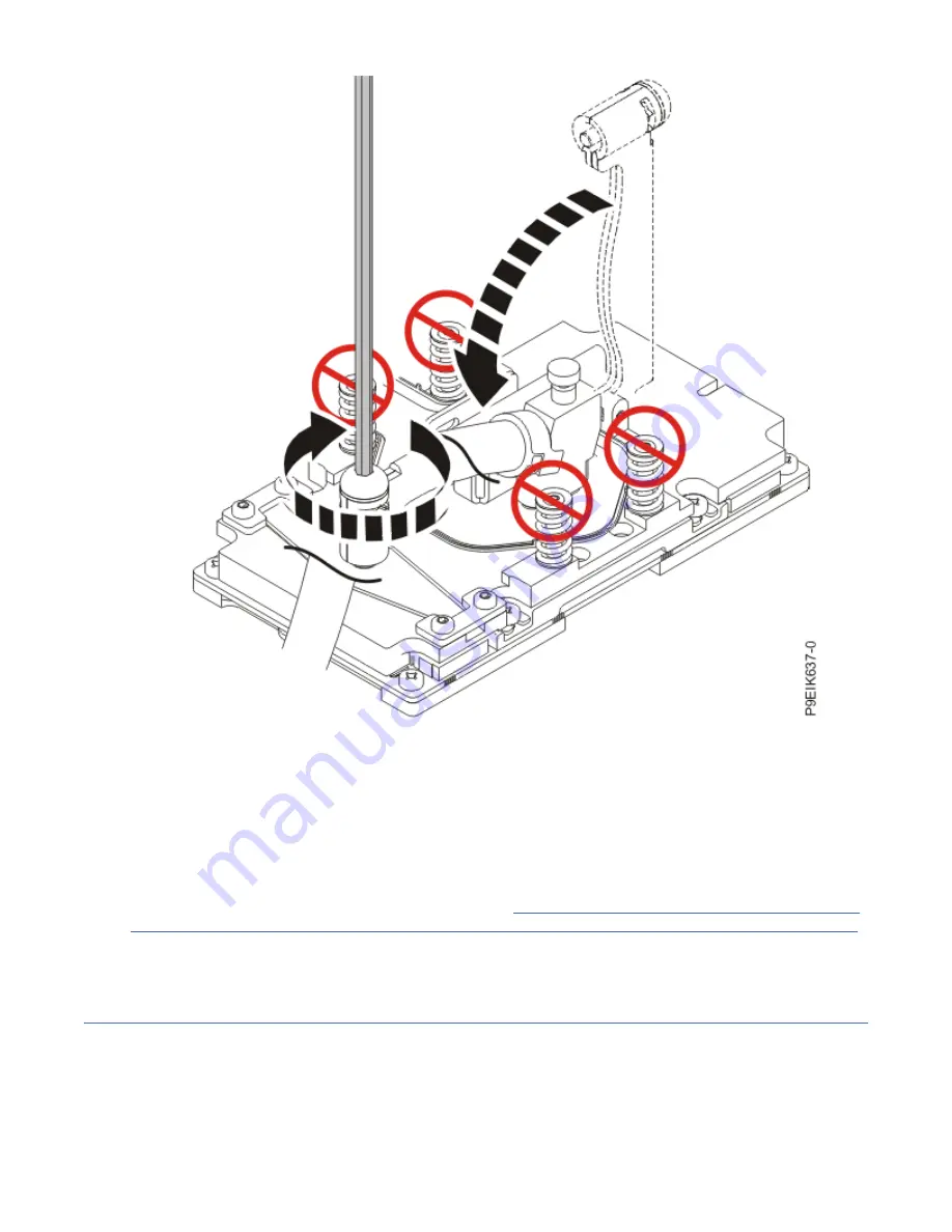
Figure 92. Secure the cold plate retainer screw

c) Return the service hook to its latched position on the bracket.

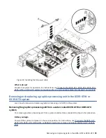
7. Replace the air baffles you removed.
8. Place the protective covers on the bottom of the replaced GPUs.

This protects the pins when returning the GPU.

What to do next
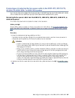
Prepare the system for operation. For instructions, see “Preparing the 8335-GTC, 8335-GTG, 8335-GTH,

8335-GTW, or 8335-GTX system for operation after you remove and replace internal parts” on page 202.

Removing and replacing memory modules in the 8335-GTW or 8335-GTX

system

Learn how to remove and replace memory modules in the system.

Removing and replacing parts in the 8335-GTW or 8335-GTX  101

Summary of Contents for Power System 8335-GTW

Page 1: ...Power Systems Servicing the 8335 GTW IBM...

Page 2: ...G229 9054 and the IBM Environmental Notices and User Guide Z125 5823 This edition applies to IBM Power Systems servers that contain the POWER9 processor and to all associated models Copyright Interna...

Page 3: ...n power cable 90 Graphics processing unit 91 Removing the graphics processing unit from a water cooled system 91 Replacing the graphics processing unit in a water cooled system 96 Memory modules 101 R...

Page 4: ...204 Starting the system 204 Stopping the 8335 GTC 8335 GTG 8335 GTH 8335 GTW or 8335 GTX system 205 Sensor status 205 Removing and replacing covers 206 Removing the service access cover 206 Installin...

Page 5: ...00 300 8751 German safety information Das Produkt ist nicht f r den Einsatz an Bildschirmarbeitspl tzen im Sinne 2 der Bildschirmarbeitsverordnung geeignet Laser safety information IBM servers can use...

Page 6: ...es To Disconnect 1 Turn off everything unless instructed otherwise 2 For AC power remove the power cords from the outlets 3 For racks with a DC power distribution panel PDP turn off the circuit breake...

Page 7: ...devices that attach to the system It is the responsibility of the customer to ensure that the outlet is correctly wired and grounded to prevent an electrical shock R001 part 1 of 2 R001 part 2 of 2 CA...

Page 8: ...zards Verify that the route that you choose can support the weight of the loaded rack cabinet Refer to the documentation that comes with your rack cabinet for the weight of a loaded rack cabinet Verif...

Page 9: ...position for example when working from a ladder Stability hazard The rack may tip over causing serious personal injury Before extending the rack to the installation position read the installation ins...

Page 10: ...uct might be equipped with multiple AC power cords or multiple DC power cables To remove all hazardous voltages disconnect all power cords and power cables L003 L007 CAUTION A hot surface nearby L007...

Page 11: ...ing into the other end of a disconnected optical fiber to verify the continuity of optic fibers may not injure the eye this procedure is potentially dangerous Therefore verifying the continuity of opt...

Page 12: ...on off smooth platforms without appreciable force so take care not to push or lean Keep riser tilt adjustable angling platform option flat at all times except for final minor angle adjustment when nee...

Page 13: ...itable for connection to intrabuilding or unexposed wiring or cabling only The intrabuilding ports of this equipment must not be metallically connected to the interfaces that connect to the OSP outsid...

Page 14: ...xiv Power Systems Servicing the 8335 GTW...

Page 15: ...IBM provided power cord for any other product Do not open or service any power supply assembly Do not connect or disconnect any cables or perform installation maintenance or reconfiguration of this p...

Page 16: ...to the outlets 5 For racks with a DC power distribution panel PDP restore the power from the Customer s DC power source and turn on the circuit breakers located in the PDP 6 Turn on the devices Sharp...

Page 17: ...ck to the rear ESD jack or to an unpainted metal surface of your hardware to prevent the electrostatic discharge from damaging your hardware When you use an ESD wrist strap follow all electrical safet...

Page 18: ...you have the electrostatic discharge ESD wrist strap on and that the ESD clip is plugged into a ground jack or connected to an unpainted metal surface If not do so now 2 Ensure that the release latch...

Page 19: ...e BMC card in the chassis 4 Using the blue tab at A and the handle B as shown in Figure 3 on page 6 press the BMC card into the connector on the system backplane Removing and replacing parts in the 83...

Page 20: ...o fully seat the card 6 Replace the four screws C to secure the BMC card to the rear of the chassis 7 If needed use your labels to replace the cables in the BMC card 8 Apply the new MAC address label...

Page 21: ...ving the cold plates from the 8335 GTW or 8335 GTX system To remove the cold plates complete the steps in this procedure Before you begin Power off the system and place it in the service position For...

Page 22: ...e ESD wrist strap must be connected to an unpainted metal surface until the service procedure is completed and if applicable until the service access cover is replaced Attention Attach an electrostati...

Page 23: ...ure 5 Removing the air baffles 3 Remove the three screws A that secure the water hoses to the rear of the system as shown in Figure 6 on page 10 Removing and replacing parts in the 8335 GTW or 8335 GT...

Page 24: ...Figure 6 Removing the rear water hose screws 4 Remove the two screws that secure the pipes to the left side of the chassis as shown in Figure 7 on page 11 10 Power Systems Servicing the 8335 GTW...

Page 25: ...side water pipe bracket 5 Remove the two pipe holders A near the middle of the system as shown in Figure 8 on page 12 Loosen the four screws B and lift the holders off the pipes Removing and replacing...

Page 26: ...ing the pipe holders 6 Remove the two pipe holders A near the front of the system as shown in Figure 9 on page 13 Loosen the four screws B and lift the holders from the pipes 12 Power Systems Servicin...

Page 27: ...re 9 Removing the pipe holders 7 Loosen the screw A that secures the pipe junction B to the front of the system as shown in Figure 10 on page 14 Removing and replacing parts in the 8335 GTW or 8335 GT...

Page 28: ...Figure 10 Loosen the front pipe screw 8 Pull the side pipes away and slightly forwards from the side of the system as shown in Figure 11 on page 15 14 Power Systems Servicing the 8335 GTW...

Page 29: ...gure 11 Loosening the side pipes 9 Lift the pipes slightly out of the chassis Rest the pipes against the side as shown in Figure 12 on page 16 Removing and replacing parts in the 8335 GTW or 8335 GTX...

Page 30: ...For each GPU loosen each of the cold plate retainer screws and swing each of the retainers open Attention Do not unscrew the four spring loaded screws that attach the aluminum heat cover to the GPU 1...

Page 31: ...late retainer 11 With the cold plate installation carrier placed on a work table open all the hook and loop fasteners on the carrier as shown in Figure 14 on page 18 Removing and replacing parts in th...

Page 32: ...teners in the cold plate installation carrier 12 Remove all the holders from the cold plate installation carrier as shown in Figure 15 on page 19 Unscrew the holders and place them on the work table 1...

Page 33: ...13 Place the cold plate installation carrier over the system as shown in Figure 16 on page 20 Ensure that the alignment pins in the carrier fit into holes for the top cover Removing and replacing par...

Page 34: ...wering the cold plate installation carrier onto the system 14 Fasten the two water hoses to the top of the cold plate installation carrier as shown in Figure 17 on page 21 20 Power Systems Servicing t...

Page 35: ...ng the hoses 15 At the rear of the system lift and fasten the rear of the side pipe to the cold plate installation carrier as shown in Figure 18 on page 22 Removing and replacing parts in the 8335 GTW...

Page 36: ...side pipe 16 At the front of the system lift the side pipe up Support it on the pins and fasten the front of the side pipe to the cold plate installation carrier as shown in Figure 19 on page 23 22 Po...

Page 37: ...side pipe 17 At the front of the system lift the front pipe junction A up Fasten the front pipe junction to the cold plate installation carrier as shown in Figure 20 on page 24 Removing and replacing...

Page 38: ...nt pipe 18 Attach the GPU cold plate to the corresponding holder a Ensure that the plastic latches are in the open position on the GPU cold plate holder as shown in Figure 21 on page 25 24 Power Syste...

Page 39: ...e GPU holder latches b Insert the cold plate pins A into the holder as shown in Figure 22 on page 25 Figure 22 Inserting the GPU cold plate pins into the holder Removing and replacing parts in the 833...

Page 40: ...ring the GPU cold plate pins d Repeat step 18 on page 24 for the other GPU cold plate 19 Fasten each GPU cold plate holder to the cold plate installation carrier as shown in Figure 24 on page 27 Use t...

Page 41: ...ssure downward on the cold plate Loosen the retainer screw of the system processor module cold plate by turning the supplied hex key counterclockwise Loosen the screw until it moves freely See Figure...

Page 42: ...processor cold plate to the holder by using the following steps a On the processor cold plate holder ensure that the plastic latches B are in the open position as shown in Figure 26 on page 29 so that...

Page 43: ...pened holder latches b Lift the coldplate straight up from the processor Insert the cold plate pins A into the holder as shown in Figure 27 on page 30 Removing and replacing parts in the 8335 GTW or 8...

Page 44: ...latches B into the narrowest part of the pin as shown in Figure 27 on page 30 d Fasten the processor cold plate holder to the cold plate installation carrier Use the alignment pin A and tighten the s...

Page 45: ...r the other processor 23 After all the cold plates are attached to the cold plate installation carrier lift the carrier straight up off the system as shown in Figure 29 on page 32 If you lift at an an...

Page 46: ...s in the cold plate installation carrier complete the steps in this procedure Before you begin To replace a faulty cold plate or water hose you first need to complete the procedure Removing the cold p...

Page 47: ...e holder from the carrier b Support the cold plate from underneath and carefully slide both of the plastic latches A to free the pins from the holder as shown in Figure 31 on page 34 Removing and repl...

Page 48: ...the work surface The cold plate is resting on the work table Repeat step 2 on page 32 for each cold plate 3 Remove each GPU cold plate from its holder a Unscrew a GPU cold plate holder from the cold p...

Page 49: ...older from the carrier b Support the cold plate from underneath and carefully slide both of the plastic latches A to free the pins from the holder as shown in Figure 33 on page 36 Removing and replaci...

Page 50: ...34 for each cold plate 4 Unfasten all the hook and loop fasteners on the cold plate installation carrier Ensure that all the water pipes are released from the holder 5 Lift the cold plate installation...

Page 51: ...nstallation carrier over the replacement cold plate assembly 6 Fasten the two water hoses to the top of the cold plate installation carrier as shown in Figure 35 on page 38 Removing and replacing part...

Page 52: ...e 35 Securing the hoses 7 At the rear of the system lift and fasten the rear of the side pipe to the cold plate installation carrier as shown in Figure 36 on page 39 38 Power Systems Servicing the 833...

Page 53: ...8 At the front of the system lift the side pipe up Support it on the pins and fasten the front of the side pipe to the cold plate installation carrier as shown in Figure 37 on page 40 Removing and re...

Page 54: ...nt of the side pipe 9 At the front of the system lift the front pipe junction A up Fasten the front pipe junction to the cold plate installation carrier as shown in Figure 38 on page 41 40 Power Syste...

Page 55: ...Attach the processor cold plates to the holder a Lift the coldplate straight up from the processor Insert the cold plate pins A into the holder as shown in Figure 39 on page 42 Removing and replacing...

Page 56: ...de both of the plastic latches A into the narrowest part of the pin c Fasten the processor cold plate holder to the cold plate installation carrier Use the alignment pin A and tighten the screw B to s...

Page 57: ...to the carrier d Repeat step 10 on page 41 for each cold plate 11 Attach the GPU cold plates to the holder a Insert the cold plate pins A into the holder as shown in Figure 41 on page 44 Removing and...

Page 58: ...the holder b Slide both of the plastic latches A into the narrowest part of the pin as shown in Figure 42 on page 44 Figure 42 Securing the GPU cold plate pins c Repeat step 11 on page 43 for each co...

Page 59: ...plates in the 8335 GTW or 8335 GTX system To replace the cold plates complete the steps in this procedure Before you begin Ensure that you have enough TIMs for the GPUs and processors Check the repla...

Page 60: ...the cold plate retainer 3 Check the TIM heat sink material For each GPU the TIM must be replaced For each processor inspect the TIM material for visible signs of damage If you see folds tears bends or...

Page 61: ...l 4 Lower the cold plate installation carrier straight down onto the system as shown in Figure 46 on page 48 If you lower the carrier at an angle the carrier catches on the cold plate clips Removing a...

Page 62: ...installation carrier onto the system 5 Replace the processor cold plates first a Unscrew a processor cold plate holder from the cold plate installation carrier as shown in Figure 47 on page 49 48 Pow...

Page 63: ...e holder from the carrier b Support the cold plate from underneath and carefully slide both of the plastic latches A to free the pins from the holder as shown in Figure 48 on page 50 Removing and repl...

Page 64: ...g the cold plate guide holes with the pins on the processor socket Keep applying light pressure downward on the cold plate to ensure that the cold plate and the processor do not move e Maintain the do...

Page 65: ...screw Repeat step 5 on page 48 for the other processor 6 Replace the GPU cold plates next a Check that the new GPU TIMs are squarely placed on the GPUs as shown in Figure 50 on page 52 Removing and re...

Page 66: ...Figure 50 Installing GPU TIMs b Unscrew a GPU cold plate holder from the cold plate installation carrier as shown in Figure 51 on page 53 52 Power Systems Servicing the 8335 GTW...

Page 67: ...older from the carrier c Support the cold plate from underneath and carefully slide both of the plastic latches A to free the pins from the holder as shown in Figure 52 on page 54 Removing and replaci...

Page 68: ...old plate onto the GPUs e Secure the middle GPU first Swing the retainer over the GPU and tighten the cold plate retainer screw as shown in Figure 53 on page 55 Repeat with the remaining clips until t...

Page 69: ...51 for the other GPU cold plate 7 Unfasten all the hook and loop fasteners on the cold plate installation carrier as shown in Figure 54 on page 56 Ensure that all the water pipes are released from th...

Page 70: ...Figure 54 Unfastening the water hoses from the carrier 8 Lift the cold plate installation carrier straight up off the system as shown in Figure 55 on page 57 56 Power Systems Servicing the 8335 GTW...

Page 71: ...rrier 9 Replace the front pipe B Use the alignment pin C to position the front pipe Tighten the screw A that secures the pipe B to the front of the system as shown in Figure 56 on page 58 Removing and...

Page 72: ...rs A near the front of the system as shown in Figure 57 on page 59 Place the pipes in the supports on the system backplane place the holders over the supports and the pipes align the screw threads at...

Page 73: ...ipes into the side of the chassis as shown in Figure 58 on page 60 Ensure the rear of the pipe slides into its position Ensure that the alignment pin at the front of the side pipe is in the pipe junct...

Page 74: ...A near the middle of the system as shown in Figure 59 on page 61 Place the pipes in the supports on the system backplane place the holders over the supports and the pipes align the screw threads at B...

Page 75: ...Replacing the middle pipe holders 13 Replace the three screws A that secure the water hoses to the rear of the system as shown in Figure 60 on page 62 Removing and replacing parts in the 8335 GTW or 8...

Page 76: ...Figure 60 Replacing the rear water hose screws 14 Replace the two screws that secure the pipes to the left side of the chassis as shown in Figure 61 on page 63 62 Power Systems Servicing the 8335 GTW...

Page 77: ...the side water pipe bracket 15 Replace the air baffles A B and C as shown in Figure 62 on page 64 The baffles go straight down you might need to maneuver them around the hoses Removing and replacing p...

Page 78: ...m for operation For instructions see Preparing the 8335 GTC 8335 GTG 8335 GTH 8335 GTW or 8335 GTX system for operation after you remove and replace internal parts on page 202 Removing and replacing a...

Page 79: ...rtant to again discharge yourself by touching an unpainted metal surface for at least 5 seconds before you continue with the service process 3 Locate the faulty drive The amber drive LED is turned on...

Page 80: ...where sdX is the drive to replace echo 0 sys block sdX device delete e Verify that you disabled the write operation on the drive by using the lsscsi command When the drive is disabled the drive no lon...

Page 81: ...ectrostatic discharge ESD wrist strap on and that the ESD clip is plugged into a ground jack or connected to an unpainted metal surface If not do so now 2 Hold the disk drive by the top and bottom edg...

Page 82: ...s You may also want to refer to Adding a Storage Device or Path https access redhat com documentation en US Red_Hat_Enterprise_Linux 7 html Storage_Administration_Guide adding_storage device or path h...

Page 83: ...elf by touching an unpainted metal surface for at least 5 seconds before you continue with the service process 2 Label and remove the fan power cable from the disk drive and fan card For instructions...

Page 84: ...g the memory air baffles 6 From the pipe bracket A near the front of the system as shown in Figure 66 on page 71 remove the three screws B that secure the bracket to the system 70 Power Systems Servic...

Page 85: ...7 From the water pipe at position C loosen the screw D as shown in Figure 66 on page 71 8 Move the water pipe and holder away from the disk drive and fan card toward the processor Removing and replac...

Page 86: ...Figure 67 Moving the front pipe away 9 Remove five screws A from the top of the disk drive and fan card See Figure 68 on page 73 for the screw locations 72 Power Systems Servicing the 8335 GTW...

Page 87: ...nd fan card b Remove one screw C from each side of the disk drive and fan card 10 The disk drive and fan card A is aligned in the system by using two pins B Pivot the disk drive and fan card away from...

Page 88: ...d jack or connected to an unpainted metal surface If not do so now 2 Remove the replacement disk drive and fan card from the protective plastic envelope 3 Using the alignment pins one on each side A f...

Page 89: ...Figure 70 Inserting the disk drive and fan card Removing and replacing parts in the 8335 GTW or 8335 GTX 75...

Page 90: ...Routing the cables under the disk drive and fan card 4 Replace two screws B for the bottom of the disk drive and fan card Figure 72 on page 77 shows the screw locations 76 Power Systems Servicing the...

Page 91: ...the disk drive and fan card b Replace one screw C in each side of the disk drive and fan card 5 Replace the water pipe and holder as shown in Figure 73 on page 78 Use the alignment pin A to align the...

Page 92: ...holder 6 For the water pipe at position C tighten the screw D as shown in Figure 74 on page 79 7 Replace the three screws B to secure the front water pipe bracket A as shown in Figure 74 on page 79 7...

Page 93: ...74 Replacing the front pipe holder 8 Replace the air baffles A and B as shown in Figure 75 on page 80 Carefully move the baffles around the hoses Removing and replacing parts in the 8335 GTW or 8335...

Page 94: ...tructions see Replacing the fan power cable in the 8335 GTC 8335 GTG 8335 GTH 8335 GTW or 8335 GTX system on page 90 What to do next Prepare the system for operation For instructions see Preparing the...

Page 95: ...our hardware to prevent the electrostatic discharge from damaging your hardware When you use an ESD wrist strap follow all electrical safety procedures An ESD wrist strap is used for static control It...

Page 96: ...ng clip on the inside wall of the system 4 Label and disconnect the disk and fan signal cable A from the disk drive and fan card B and from the system backplane C Using your thumb press the release la...

Page 97: ...edure 1 Ensure that you have the electrostatic discharge ESD wrist strap on and that the ESD clip is plugged into a ground jack or connected to an unpainted metal surface If not do so now 2 Using the...

Page 98: ...internal parts on page 202 Removing and replacing fans in the 8335 GTW or 8335 GTX system Learn how to remove and replace the fans in the system Removing a fan from the 8335 GTW or 8335 GTX system To...

Page 99: ...equipment If you do not have an ESD wrist strap just prior to removing the product from ESD packaging and installing or replacing hardware touch an unpainted metal surface of the system for a minimum...

Page 100: ...clip is plugged into a ground jack or connected to an unpainted metal surface If not do so now 2 Using your hand to support the bottom of the fan align the fan A with the fan slot and slide it into t...

Page 101: ...cover is replaced Attention Attach an electrostatic discharge ESD wrist strap to the front ESD jack to the rear ESD jack or to an unpainted metal surface of your hardware to prevent the electrostatic...

Page 102: ...s 3 Grasp the connector end of the fan power cable that is connected to the power riser See A in Figure 82 on page 90 4 While you press the latch release lever with your thumb disconnect the cable fro...

Page 103: ...cable and the connector 5 Disconnect the fan power cable connector end from the disk drive and fan card 6 Lift the fan power cable to remove it from the system Be careful to ensure that the ends of t...

Page 104: ...wrist strap on and that the ESD clip is plugged into a ground jack or connected to an unpainted metal surface If not do so now 2 Route the fan power cable A connector end through the opening and conne...

Page 105: ...earn how to remove and replace a graphics processing unit GPU in the system Removing the graphics processing unit from a water cooled 8335 GTW or 8335 GTX system To remove a graphics processing unit f...

Page 106: ...procedures An ESD wrist strap is used for static control It does not increase or decrease your risk of receiving electric shock when using or working on electrical equipment If you do not have an ESD...

Page 107: ...cold plate retainer b Lift the cold plate A off the GPUs that you are removing and attach the cold plate to the service hook B as shown in Figure 85 on page 94 Removing and replacing parts in the 8335...

Page 108: ...h to clip 5 For the GPU you are removing remove the eight screws shown in Figure 86 on page 95 Attention Do not unscrew the four spring loaded screws that attach the aluminum heat cover to the GPU 94...

Page 109: ...osen the four spring loaded screws 6 Remove the GPU from the system backplane Be careful of the pins on the bottom of the GPUs to avoid damaging the pins and the GPU See Figure 87 on page 96 Removing...

Page 110: ...D wrist strap on and that the ESD clip is plugged into a ground jack or connected to an unpainted metal surface If not do so now 2 Remove the GPU from the protective packaging Remove the protective co...

Page 111: ...98 Start with the inner four screws Thread the inner four screws half way using the sequence that is shown Once all four screws are threaded then fully tighten them Next tighten the outer four screws...

Page 112: ...into GPU socket 5 Place a new TIM on each of the aluminum heat covers of each GPU for the cold plate that you are replacing See Figure 90 on page 99 for the orientation The part number is 00E5133 98...

Page 113: ...ation 6 Replace the GPU cold plate a Unhook the cold plate A from the service hook B and carefully align the cold plate on 2 or 3 GPUs See Figure 91 on page 100 Removing and replacing parts in the 833...

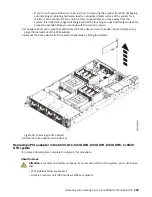
Page 114: ...b Beginning with the middle GPU swing the retainer over the GPU and code plate then tighten the cold plate retainer screw as shown in Figure 92 on page 101 Repeat this step for each of the remaining...

Page 115: ...pins when returning the GPU What to do next Prepare the system for operation For instructions see Preparing the 8335 GTC 8335 GTG 8335 GTH 8335 GTW or 8335 GTX system for operation after you remove a...

Page 116: ...metal surface of your hardware to prevent the electrostatic discharge from damaging your hardware When you use an ESD wrist strap follow all electrical safety procedures An ESD wrist strap is used for...

Page 117: ...igure 93 Removing the memory air baffles 3 Locate the memory module to remove Figure 94 on page 104 shows the location of the memory modules Removing and replacing parts in the 8335 GTW or 8335 GTX 10...

Page 118: ...e from the slot a Unlock the memory module by pushing the locking tabs away from the memory module in the direction shown in Figure 95 on page 105 The lever action of opening the tabs pushes the memor...

Page 119: ...f the slot 5 Place the memory module on an ESD mat Replace 6 To replace a memory module complete the following steps a Push the locking tabs to the open position away from the slot in the direction sh...

Page 120: ...lled incorrectly Note the location of the key tab within the memory connector before you attempt to install it c Press firmly on each side of the memory module until the locking tab locks in place wit...

Page 121: ...ry placement rules for the system The system has memory configurations of 128 GB 256 GB 512 GB 1024 GB or 2048 GB All memory modules must be installed and must be of the same size and type The system...

Page 122: ...uctions see Preparing the 8335 GTC 8335 GTG 8335 GTH 8335 GTW or 8335 GTX system to remove and replace internal parts on page 198 About this task Attention For safety and airflow purposes if you remov...

Page 123: ...from the PCIe adapter Also if needed label and remove any plugs that extend out of the PCIe adapter 3 Remove the PCIe adapter from the system backplane by lifting the adapter Figure 98 Removing a PCI...

Page 124: ...gs that you removed from the PCIe adapter Using your labels insert the cables into the PCIe adapter What to do next Prepare the system for operation For instructions see Preparing the 8335 GTC 8335 GT...

Page 125: ...ures An ESD wrist strap is used for static control It does not increase or decrease your risk of receiving electric shock when using or working on electrical equipment If you do not have an ESD wrist...

Page 126: ...wer cords The product might be equipped with multiple AC power cords or multiple DC power cables To remove all hazardous voltages disconnect all power cords and power cables L003 L005 112 Power System...

Page 127: ...its position in the system pull the locking tab A to the left b Grasp the power supply handle with one hand and pull the power supply B partially out of the system c Place your other hand underneath...

Page 128: ...the power supply b Align the power supply A with the bay with the fan to the left c Slide the power supply into the system until the latch B locks in place d Repeat steps 2 a on page 114 2 c on page 1...

Page 129: ...ocedures An ESD wrist strap is used for static control It does not increase or decrease your risk of receiving electric shock when using or working on electrical equipment If you do not have an ESD wr...

Page 130: ...02 Removing the power switch and cable from the system backplane 4 Remove the rack installation support from the side of the system as shown in Figure 103 on page 117 116 Power Systems Servicing the 8...

Page 131: ...Figure 103 Removing the rack installation support 5 Remove the top and side screws from the power switch as shown in Figure 104 on page 118 Removing and replacing parts in the 8335 GTW or 8335 GTX 117...

Page 132: ...Figure 104 Remove the top and side screws 6 Pull the power switch from the system as shown in Figure 105 on page 119 118 Power Systems Servicing the 8335 GTW...

Page 133: ...e electrostatic discharge ESD wrist strap on and that the ESD clip is plugged into a ground jack or connected to an unpainted metal surface If not do so now 2 Find the replacement power switch and cab...

Page 134: ...gure 106 Replacing the power switch and cable into the system backplane 4 Replace the top and side screws for the power switch as shown in Figure 107 on page 121 120 Power Systems Servicing the 8335 G...

Page 135: ...5 Using the labels plug the power switch and cable A to the system backplane as shown in Figure 108 on page 122 Ensure that the cable latch clip snaps into place on the connectors Removing and replac...

Page 136: ...Figure 108 Plugging in the power switch and cable 6 Replace the rack installation support on the side of the system as shown in Figure 109 on page 123 122 Power Systems Servicing the 8335 GTW...

Page 137: ...internal parts on page 202 Removing and replacing the system backplane in the 8335 GTW Learn how to remove and replace the system backplane in the IBM Power System AC922 8335 GTW and 8335 GTX system P...

Page 138: ...are removed from the system processor modules and GPUs Each module and GPU must have thermal interface material TIM between the module the GPU and the cold plate If the processor TIM is damaged it mus...

Page 139: ...ng the disk and fan signal cable from the 8335 GTC 8335 GTG 8335 GTH 8335 GTW or 8335 GTX system on page 81 6 Label and remove the fan power cable from the system backplane For instructions see Removi...

Page 140: ...module 10 Remove dust and debris from the system processor module area If dust or debris is present use the supplied air pump to clean the system processor module area Blow small bursts of air from t...

Page 141: ...repare the system processor module for removal a Open the latches that hold the system processor module in the supplied removal tool A Push down on the ring B while pressing in on the tabs C See Figur...

Page 142: ...oval tool latches b Lower the tool over the system processor module while ensuring that the two guide pins A insert into the alignment holes B on each side of the tool See Figure 114 on page 129 128 P...

Page 143: ...on top of the system processor module push down on the ring A to close the latches C and lock the system processor module into the tool Make sure that both of the tool jaws are locked on the system pr...

Page 144: ...socket Place them at an angle in the top cover of the system processor module packaging as shown in Figure 116 on page 131 Note Set the tool and system processor module at an angle on the top cover of...

Page 145: ...ver of the packaging 13 Open the latches that hold the system processor module in the supplied removal tool A Push down on the ring B while pressing in on the tabs C See Figure 117 on page 132 Removin...

Page 146: ...Figure 117 Releasing the system processor module from the tool 14 Remove one screw B from each side of the middle support A See Figure 118 on page 133 132 Power Systems Servicing the 8335 GTW...

Page 147: ...nd supports The screw locations are shown in Figure 119 on page 134 The screws at A are the shortest The screws at B and C are longer and secure the pipe supports The three metal pipe supports at B an...

Page 148: ...Figure 119 System backplane screw locations 16 Using the two blue handles A lift the system backplane B straight up to remove it See Figure 120 on page 135 134 Power Systems Servicing the 8335 GTW...

Page 149: ...nsure that you have the electrostatic discharge ESD wrist strap on and that the ESD clip is plugged into a ground jack or connected to an unpainted metal surface If not do so now 2 Remove the replacem...

Page 150: ...ts and C one longer support Align and tighten the 22 screws into the system backplane at A and into the pipe supports at B and C The screw locations are shown in Figure 122 on page 137 The screws at A...

Page 151: ...Figure 122 System backplane screw locations 5 Ensure that the jumper shown in Figure 123 on page 138 is set to the water cooled position Removing and replacing parts in the 8335 GTW or 8335 GTX 137...

Page 152: ...Figure 123 Jumper in water cooled position 6 Replace one screw B on each side of the middle support A See Figure 124 on page 139 138 Power Systems Servicing the 8335 GTW...

Page 153: ...it in a water cooled 8335 GTW or 8335 GTX system on page 96 8 On the new system backplane remove the socket cover from a system processor socket 9 Prepare the system processor module for installation...

Page 154: ...oval tool latches b Lower the tool over the system processor module while ensuring that the two guide pins A insert into the alignment holes B on each side of the tool See Figure 126 on page 141 140 P...

Page 155: ...on top of the system processor module push down on the ring A to close the latches C and lock the system processor module into the tool Make sure that both of the tool jaws are locked on the system pr...

Page 156: ...e tool out of the system processor module tray 11 Install the system processor module a If dust or debris is present on the system processor socket use the supplied air pump to clean the socket Blow s...

Page 157: ...r the tool evenly without tilting the tool See Figure 129 on page 144 Note Do not attempt to slide the tool and the system processor module in any direction while the system processor module is touchi...

Page 158: ...m processor module c Open the latches that hold the system processor module in the supplied removal tool A Push down on the ring B while pressing in on the tabs C See Figure 130 on page 145 144 Power...

Page 159: ...the system processor module 12 Inspect the thermal interface material TIM for visible signs of damage as shown in Figure 131 on page 146 If you see folds tears bends or if you have doubts about the TI...

Page 160: ...eat sink a Open the TIM packaging and carefully remove the TIM holding it by the edges of the carrier strip and holding it away from the shipping container b Remove the protective film from the clear...

Page 161: ...undamaged TIM and heat sink a Using the tweezers move the old TIM from the clean dry surface and center it onto the new system processor module The TIM has no preferred up side The TIM can be placed o...

Page 162: ...5 GTC 8335 GTG 8335 GTH 8335 GTW or 8335 GTX system on page 90 19 Using your labels replace the disk and fan signal cable into that connector in the system backplane For instructions see Replacing the...

Page 163: ...re the system for operation after replacing the system backplane complete the steps in this procedure Procedure 1 Prepare the system for operation For instructions see Preparing the 8335 GTC 8335 GTG...

Page 164: ...led a Update the machine serial number by running the following command replacing 1234567 with your seven character serial number The command must be run after the system is powered on opt openpower l...

Page 165: ...SD wrist strap follow all electrical safety procedures An ESD wrist strap is used for static control It does not increase or decrease your risk of receiving electric shock when using or working on ele...

Page 166: ...air baffles 4 Remove the cold plate from the system processor module a Apply light pressure downward on the cold plate Loosen the retainer screw of the system processor module cold plate by turning th...

Page 167: ...module and attach the protective cover B to the cold plate as shown in Figure 138 on page 153 Figure 138 Removing the cold plate and attaching the protective cover c Move the cold plate and cover off...

Page 168: ...module 6 Remove dust and debris from the system processor module area If dust or debris is present use the supplied air pump to clean the system processor module area Blow small bursts of air from th...

Page 169: ...epare the system processor module for removal a Open the latches that hold the system processor module in the supplied removal tool A Push down on the ring B while pressing in on the tabs C See Figure...

Page 170: ...oval tool latches b Lower the tool over the system processor module while ensuring that the two guide pins A insert into the alignment holes B on each side of the tool See Figure 142 on page 157 156 P...

Page 171: ...on top of the system processor module push down on the ring A to close the latches C and lock the system processor module into the tool Make sure that both of the tool jaws are locked on the system pr...

Page 172: ...socket Place them at an angle in the top cover of the system processor module packaging as shown in Figure 144 on page 159 Note Set the tool and system processor module at an angle on the top cover of...

Page 173: ...ver of the packaging 9 Open the latches that hold the system processor module in the supplied removal tool A Push down on the ring B while pressing in on the tabs C See Figure 145 on page 160 Removing...

Page 174: ...lugged into a ground jack or connected to an unpainted metal surface If not do so now 2 Remove dust and debris from the system processor socket area If dust or debris is present use the supplied air p...

Page 175: ...latches b Lower the tool over the system processor module while ensuring that the two guide pins A insert into the alignment holes B on each side of the tool See Figure 147 on page 162 Removing and re...

Page 176: ...l sitting on top of the system processor module push down on the ring A to close the latches C and lock the system processor module into the tool Make sure that both of the tool jaws are locked on the...

Page 177: ...of the system processor module tray 5 Install the system processor module a If dust or debris is present on the system processor socket use the supplied air pump to clean the socket Blow small bursts...

Page 178: ...re to lower the tool evenly without tilting the tool See Figure 150 on page 165 Note Do not attempt to slide the tool and the system processor module in any direction while the system processor module...

Page 179: ...r module c Open the latches that hold the system processor module in the supplied removal tool A Push down on the ring B while pressing in on the tabs C See Figure 151 on page 166 Removing and replaci...

Page 180: ...tool off the system processor module 6 Inspect the thermal interface material TIM for visible signs of damage as shown in Figure 152 on page 167 If you see folds tears bends or if you have doubts abo...

Page 181: ...pen the TIM packaging and carefully remove the TIM holding it by the edges of the carrier strip and holding it away from the shipping container b Remove the protective film from the clear carrier stri...

Page 182: ...existing undamaged TIM and heat sink a Using the tweezers move the old TIM from the clean dry surface and center it onto the new system processor module The TIM has no preferred up side The TIM can be...

Page 183: ...rotective cover B from the cold plate A as shown in Figure 155 on page 169 Figure 155 Removing the protective cover from the cold plate b Using the alignment pins carefully place the cold plate straig...

Page 184: ...ove d Tighten the cold plate retainer screw with the supplied hex key as shown in Figure 156 on page 170 Figure 156 Tightening the cold plate retainer screw 11 Replace the air baffles A and B as shown...

Page 185: ...replaced by the edges and lift it off the packaging cover Align the beveled corner of the module A to the corner of the packaging with triangle B and place it in the packaging as shown in Figure 158 o...

Page 186: ...mixing system processors with different DDx y levels You should only complete this procedure if you are removing and replacing all of the system processor modules with new system processor modules Pro...

Page 187: ...wrist strap to the front ESD jack to the rear ESD jack or to an unpainted metal surface of your hardware to prevent the electrostatic discharge from damaging your hardware When you use an ESD wrist s...

Page 188: ...ackplane Replacing 3 Insert the time of day battery in the slot on the system backplane as shown in Figure 160 on page 175 Ensure to insert the battery with the correct polarity as recorded during rem...

Page 189: ...e water manifold in the IBM Power System AC922 8335 GTW and 8335 GTX system Preparing the 8335 GTW or 8335 GTX system to remove and replace the water manifold To prepare the system to remove and repla...

Page 190: ...ng power cords from an 8335 GTC 8335 GTG 8335 GTH 8335 GTW or 8335 GTX system on page 214 Note The system might be equipped with redundant power supply Before you continue with this procedure ensure t...

Page 191: ...rns or both L005 5 Remove the power supplies from the system as shown in Figure 161 on page 178 a To release a power supply from its position in the system pull the locking tab A to the left b Grasp t...

Page 192: ...e rack 7 Label and disconnect the external cables that are connected to the systems that are in the rack 8 Label and disconnect the water hoses at the manifold for each server in the rack Pull the cou...

Page 193: ...e of the rack where the manifold is mounted 11 Repeat step 7 on page 178 through step 10 on page 179 for each system in the rack Removing the water manifold from the 8335 GTW or 8335 GTX system To rem...

Page 194: ...1 on page 179 to close the valve of the facility water return hose 3 Twist the quick connect ball valve fittings on the manifold hose and on the facility water supply hose a quarter turn in the direct...

Page 195: ...p 3 on page 180 to disconnect the facility water return hose 5 Loosen the four nuts that attach the manifold to the mounting brackets by using a 7 mm nut driver Then remove the manifold Removing and r...

Page 196: ...ld a Have a bucket ready to collect the water of at least 2 gallons b Hold the manifold upright with the hoses face down c Take one of the manifold quick connect valves and hold it over the bucket d T...

Page 197: ...8335 GTX system To replace a water manifold complete the steps in this procedure Procedure 1 If the original manifold had the facility supply and return water hoses that exit at the top of the rack c...

Page 198: ...is lower than the return manifold half Align the Z brackets to the manifold Use the labels on the bracket and the manifold to properly align the brackets Then by using a 7 mm nut driver reattach the m...

Page 199: ...e 168 Installing the manifold z brackets 2 Align the manifold to the mounting bracket slots then attach the manifold by using a 7 mm nut driver Removing and replacing parts in the 8335 GTW or 8335 GTX...

Page 200: ...Align the two quick connect ball valve fittings then turn the fittings a quarter turn to lock the fittings Then press the pin on the lever and turn the lever 90 degrees to open one side of the valve T...

Page 201: ...he side of the rack where the manifold is mounted 2 Replace the system into the rack CAUTION This system requires two people to replace the system into the rack If your rack has slider rails replace t...

Page 202: ...plies as shown in Figure 172 on page 189 a Place your other hand underneath the power supply b Align the power supply A with the bay with the fan to the left c Slide the power supply into the system u...

Page 203: ...teps 6 on page 188 7 on page 189 for all the systems in the rack 9 Start the system For instructions see Starting the 8335 GTC 8335 GTG 8335 GTH 8335 GTW or 8335 GTX system on page 204 10 Repeat step...

Page 204: ...190 Power Systems Servicing the 8335 GTW...

Page 205: ...er disconnect all power cords from their AC power source For racks with a DC power distribution panel PDP disconnect the customer s DC power source to the PDP When connecting power to the product ensu...

Page 206: ...1 part 1 of 2 DANGER Observe the following precautions when working on or around your IT rack system Heavy equipment personal injury or equipment damage might result if mishandled Always lower the lev...

Page 207: ...ised Ensure that air flow is not blocked or reduced on any side front or back of a unit used for air flow through the unit Consideration should be given to the connection of the equipment to the suppl...

Page 208: ...wer cords The product might be equipped with multiple AC power cords or multiple DC power cables To remove all hazardous voltages disconnect all power cords and power cables L003 L005 194 Power System...

Page 209: ...ons The provider of your parts or next level of support In the United States the IBM Rochester Manufacturing Automated Information Line R MAIL at 1 800 300 8751 In countries and regions outside of the...

Page 210: ...es standby power to the unit The blue LED is used to identify the system that requires service The amber LED indicates a problem in the system After a part is repaired the amber LED takes a minute to...

Page 211: ...t needs servicing Learn how to turn on the blue identify LED to help you find the system that needs servicing Procedure To activate the blue system identify LED use the following command openbmctool U...

Page 212: ...used for static control It does not increase or decrease your risk of receiving electric shock when using or working on electrical equipment If you do not have an ESD wrist strap just prior to removi...

Page 213: ...or or or or Common procedures for servicing or installing features in the 8335 GTC 8335 GTG 8335 GTH 8335 GTW or 8335 GTX system 199...

Page 214: ...d metal burns or both L005 9 Remove the power supplies from the system as shown in Figure 176 on page 201 a To release a power supply from its position in the system pull the locking tab A to the left...

Page 215: ...not place any object on top of a rack mounted device unless that rack mounted device is intended for use as a shelf R008 L012 CAUTION Pinch hazard L012 11 Remove the service access cover For instructi...

Page 216: ...ng the service access cover on an 8335 GTC 8335 GTG 8335 GTH 8335 GTW or 8335 GTX system on page 207 3 Place the system into the operating position For instructions see Placing an 8335 GTC 8335 GTG 83...

Page 217: ...tructions see Configuring the BMC IP address www ibm com support knowledgecenter POWER9 p9eih p9eih_configuring_bmc_ip htm 10 Enter the network settings that you recorded earlier For instructions see...

Page 218: ...is procedure to power on the system or you can use a console to power on the system Procedure 1 Open the front rack door if necessary 2 Before you press the power button ensure that the power supplies...

Page 219: ...determine the general health of the system without using the event codes To view the sensor status use the following command openbmctool U username P password H BMC IP address or BMC host name fru sta...

Page 220: ...5 GTX system To remove the service access cover complete the steps in this procedure Procedure 1 Ensure that you removed both power supplies from the system For instructions see Preparing the 8335 GTC...

Page 221: ...ice access cover complete the steps in this procedure About this task Attention For safety airflow purposes and thermal performance the service access cover must be installed and fully seated before p...

Page 222: ...ary open the front rack door 2 Ensure that you have the electrostatic discharge ESD wrist strap on and that the ESD clip is plugged into a ground jack or connected to an unpainted metal surface If not...

Page 223: ...ng position Placing an 8335 GTC 8335 GTG 8335 GTH 8335 GTW or 8335 GTX system into the service position To place a system into the service position complete the steps in this procedure About this task...

Page 224: ...to remove the system from the rack Note When you place the system into the service position you must ensure that all stability plates are firmly installed to prevent the rack from toppling Ensure that...

Page 225: ...erson on the right side of the system 6 Tilt and lift the system from the rails 7 Carefully set the system on a table with an appropriate ESD surface Placing an 8335 GTC 8335 GTG 8335 GTH 8335 GTW or...

Page 226: ...m unit back into the rack Procedure 1 Unlock the blue rail safety latches A by lifting them upward 2 Align the system unit on to the rails and push the system unit back into the rack until both releas...

Page 227: ...the system into position over the fixed rack rails 4 Carefully lower the system until the rear of the system rests on the rails 5 While one person is supporting the weight of the system have the secon...

Page 228: ...tem Disconnecting power cords from an 8335 GTC 8335 GTG 8335 GTH 8335 GTW or 8335 GTX system To disconnect a power cord complete the steps in this procedure Procedure 1 Open the rear rack door on the...

Page 229: ...187 on page 216 shows how to loop the cables Figure 186 Routing the power cord loop in the cable management arm Common procedures for servicing or installing features in the 8335 GTC 8335 GTG 8335 GT...

Page 230: ...tem unit as shown in Figure 188 on page 217 Note This system might be equipped with two or more power supplies If the removing and replacing procedures require the power to be off then ensure that all...

Page 231: ...r labels reconnect the power cords to the system unit as shown in Figure 189 on page 217 Figure 189 Connecting the power cords to the system 3 Loop and attach the power cords to the power supply handl...

Page 232: ...Figure 190 on page 218 and Figure 191 on page 219 shows how to loop the cables Figure 190 Routing the power cord loop in the cable management arm 218 Power Systems Servicing the 8335 GTW...

Page 233: ...1 Power cord loop with sidewall routing 4 Close the rack door at the rear of the system Common procedures for servicing or installing features in the 8335 GTC 8335 GTG 8335 GTH 8335 GTW or 8335 GTX sy...

Page 234: ...220 Power Systems Servicing the 8335 GTW...

Page 235: ...ct s and or the program s described in this publication at any time without notice Any references in this information to non IBM websites are provided for convenience only and do not in any manner ser...

Page 236: ...sion to use information technology content successfully Overview The IBM Power Systems servers include the following major accessibility features Keyboard only operation Operations that use a screen r...

Page 237: ...eployed for this Software Offering provide you as the customer the ability to collect personally identifiable information from end users via cookies and other technologies you should seek your own leg...

Page 238: ...interference caused by using other than recommended cables and connectors or by unauthorized changes or modifications to this equipment Unauthorized changes or modifications could void the user s auth...

Page 239: ...nt explains the Japan Electronics and Information Technology Industries Association JEITA statement for products less than or equal to 20 A per phase This statement explains the JEITA statement for pr...

Page 240: ...nn das Produkt ohne Zustimmung von IBM ver ndert bzw wenn Erweiterungskomponenten von Fremdherstellern ohne Empfehlung von IBM gesteckt eingebaut werden EN 55022 EN 55032 Klasse A Ger te m ssen mit fo...

Page 241: ...ur in a particular installation If this equipment does cause harmful interference to radio or television reception which can be determined by turning the equipment off and on the user is encouraged to...

Page 242: ...chnical Regulations Abteilung M456 IBM Allee 1 71139 Ehningen Germany Tel 49 800 225 5426 email halloibm de ibm com VCCI Statement Japan Japan Electronics and Information Technology Industries Associa...

Page 243: ...hland Einhaltung des Gesetzes ber die elektromagnetische Vertr glichkeit von Ger ten Dieses Produkt entspricht dem Gesetz ber die elektromagnetische Vertr glichkeit von Ger ten EMVG Dies ist die Umset...

Page 244: ...ise without the express consent of IBM Rights Except as expressly granted in this permission no other permissions licenses or rights are granted either express or implied to the publications or any in...

Page 245: ......

Page 246: ...IBM...

Reviews: