background image

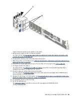
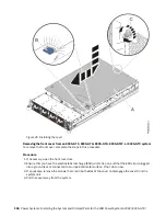
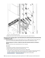
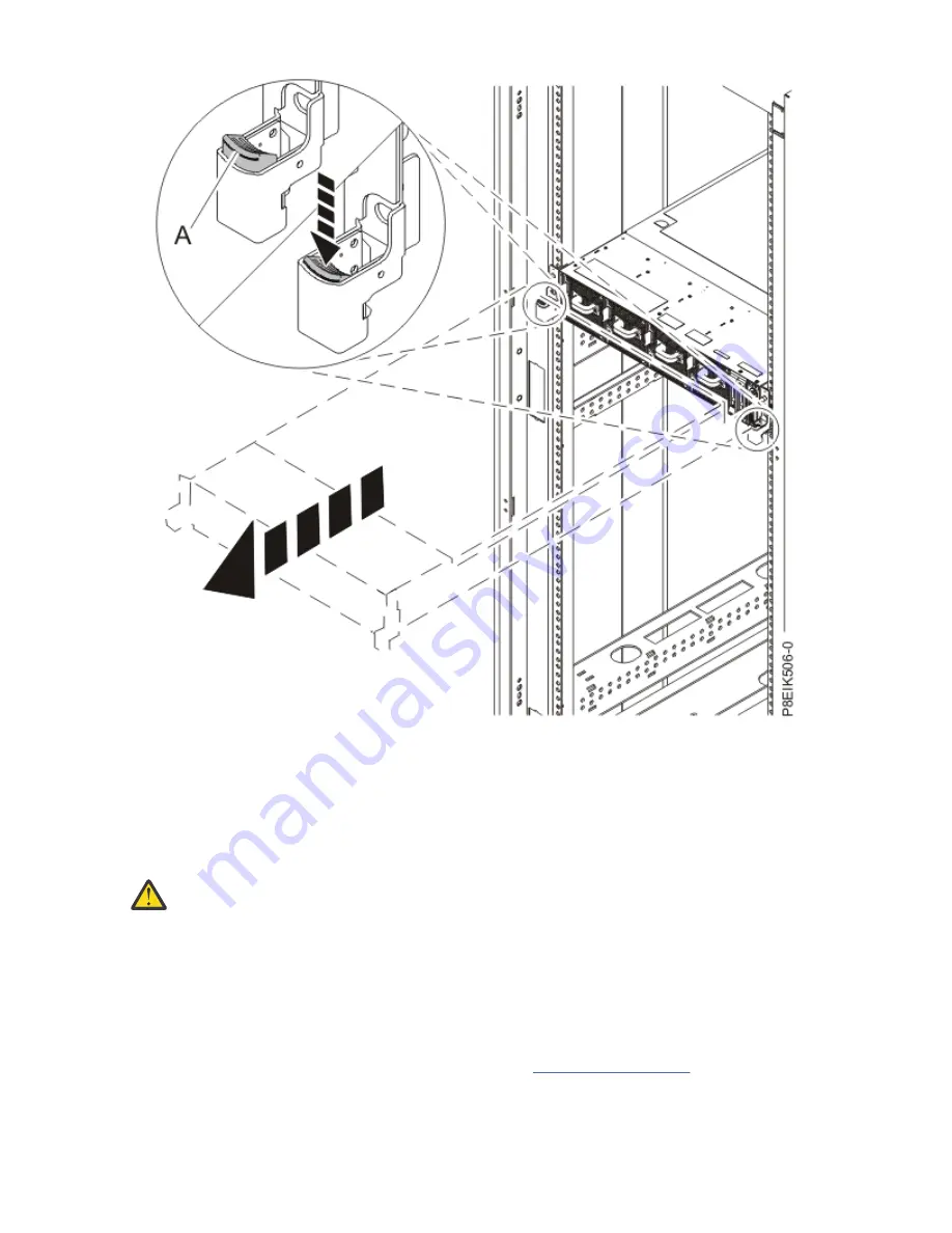
Figure 50. Placing the system into the service position

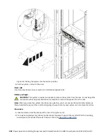
3. Pull the system unit out of the rack.

Fixed rails

Use this procedure when your system is installed using fixed rails.

Before you begin

CAUTION: This system requires two people to remove the system from the rack. Do not begin this

procedure unless physical assistance is available to remove the system from the rack.

Note: When you place the system into the service position, you must ensure that all stability plates are

firmly installed to prevent the rack from toppling. Ensure that only one system unit is removed at a time.

Procedure

1. Label and disconnect the cables at the rear of the system unit.
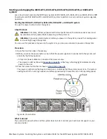
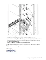
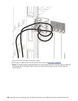
2. For a water-cooled system, label and disconnect the water hoses at the manifold. Pull the coupling

toward you to disconnect the water hoses as shown in Figure 51 on page 103.

102  Power Systems: Installing the System and Ordered Parts for the IBM Power System AC922 (8335-GTX)

Summary of Contents for Power System AC922

Page 1: ...Power Systems Installing the System and Ordered Parts for the IBM Power System AC922 8335 GTX IBM...

Page 2: ...G229 9054 and the IBM Environmental Notices and User Guide Z125 5823 This edition applies to IBM Power Systems servers that contain the POWER9 processor and to all associated models Copyright Interna...

Page 3: ...GTG 8335 GTH or 8335 GTX system 20 PCIe adapters by feature code 22 Installing a PCIe adapter in the 8335 GTG 8335 GTH or 8335 GTX system 79 Common procedures for servicing or installing features 82...

Page 4: ...iv...

Page 5: ...00 300 8751 German safety information Das Produkt ist nicht f r den Einsatz an Bildschirmarbeitspl tzen im Sinne 2 der Bildschirmarbeitsverordnung geeignet Laser safety information IBM servers can use...

Page 6: ...verything unless instructed otherwise 2 For AC power remove the power cords from the outlets 3 For racks with a DC power distribution panel PDP turn off the circuit breakers located in the PDP and rem...

Page 7: ...devices that attach to the system It is the responsibility of the customer to ensure that the outlet is correctly wired and grounded to prevent an electrical shock R001 part 1 of 2 R001 part 2 of 2 CA...

Page 8: ...hat you choose can support the weight of the loaded rack cabinet Refer to the documentation that comes with your rack cabinet for the weight of a loaded rack cabinet Verify that all door openings are...

Page 9: ...position for example when working from a ladder Stability hazard The rack may tip over causing serious personal injury Before extending the rack to the installation position read the installation ins...

Page 10: ...ultiple AC power cords or multiple DC power cables To remove all hazardous voltages disconnect all power cords and power cables L003 L007 CAUTION A hot surface nearby L007 x Power Systems Installing t...

Page 11: ...ing into the other end of a disconnected optical fiber to verify the continuity of optic fibers may not injure the eye this procedure is potentially dangerous Therefore verifying the continuity of opt...

Page 12: ...out appreciable force so take care not to push or lean Keep riser tilt adjustable angling platform option flat at all times except for final minor angle adjustment when needed Do not stand under overh...

Page 13: ...itable for connection to intrabuilding or unexposed wiring or cabling only The intrabuilding ports of this equipment must not be metallically connected to the interfaces that connect to the OSP outsid...

Page 14: ...xiv Power Systems Installing the System and Ordered Parts for the IBM Power System AC922 8335 GTX...

Page 15: ...ions servlet pbi wss This bulletin provides a list of the key IBM system installation activities and a list of activities that might be billable Installing the 8335 GTX system Learn how to install cab...

Page 16: ...ead the Rack safety notices http www ibm com support knowledgecenter POWER9 p9hbf p9hbf_racksafety htm 2 Determine where to place the system unit in the rack As you plan for installing the system unit...

Page 17: ...ft side of the rack 6 Go to the rear of the rack 7 On the right side find the EIA unit that corresponds to the bottom EIA unit marked on the front of the rack 8 Mark the bottom EIA unit 9 Mark the cor...

Page 18: ...4 through 6 on page 4 for the left rail 8 Secure both rails to the front EIA support flange by using two M5 x 16 mm screws Install the screws through the pins that you attached 9 Secure both rails to...

Page 19: ...anifold as shown in the following figure Ensure that you plug the male hose into the female manifold plug and plug the female hose into the male manifold plug Attention Before powering on the system e...

Page 20: ...server 10 Plug the system power cords and the power cords for any other attached devices into the AC power source 11 Continue with Completing server setup on page 8 Setting up a preinstalled server Us...

Page 21: ...d Note Your order information is included with your product You can also obtain the order information from your marketing representative or the IBM Business Partner If you have incorrect missing or da...

Page 22: ...rds for any other attached devices into the AC power source 6 Continue with Completing server setup on page 8 Completing server setup Learn how to complete server setup Before you begin Note You might...

Page 23: ...lect Power Firmware find your machine type and model and click Subscribe f Exit the Browse for a product screen g Click Delivery preferences to set email preferences and click Submit h Click Edit to s...

Page 24: ...e find your machine type and model and click Subscribe f Exit the Browse for a product screen g Click Delivery preferences to set email preferences and click Submit h Click Edit to select the types of...

Page 25: ...strap follow all electrical safety procedures An ESD wrist strap is used for static control It does not increase or decrease your risk of receiving electric shock when using or working on electrical e...

Page 26: ...ttom edges as you position the disk drive and insert it into the disk drive slot Important Ensure that the disk drive is fully seated and is all the way into the system 6 Lock the disk drive bay handl...

Page 27: ...proceed to verifying that the new disk drive is active To run the rescan scsi bus command in the Ubuntu Linux operating system log in to the system as the root user and run the following command resc...

Page 28: ...y modules The supported memory module sizes are either 8 GB 16 GB 32 GB or 128 GB Mixing of memory module feature codes is not allowed Table 1 on page 14 lists the supported memory feature codes Table...

Page 29: ...ing hardware touch an unpainted metal surface of the system for a minimum of 5 seconds If at any point in this service process you move away from the system it is important to again discharge yourself...

Page 30: ...k each memory module by pushing the locking tabs away from the memory module in the direction shown in Figure 10 on page 17 The lever action of opening the tabs pushes the memory module out of the slo...

Page 31: ...n ESD mat 6 Repeat steps 4 on page 16 5 on page 17 until all the memory modules are removed Install the memory modules 7 To install memory modules complete the following steps a Push the locking tabs...

Page 32: ...ory connector before you attempt to install it c Press firmly on each side of the memory module until the locking tab locks in place with an audible click 8 Repeat step 7 on page 17 until all of the m...

Page 33: ...tion about removing installing using and managing Peripheral Component Interconnect Express PCIe adapters for the system Installing this feature is a customer task You can complete this task yourself...

Page 34: ...onent Interconnect Express PCIe adapters that are supported for the system PCIe slot descriptions The system provides PCIe generation 4 slots Table 3 on page 20 lists the PCIe adapter slots and detail...

Page 35: ...nnectX 5 CAPI capable adapter FC EC64 CCIN 2CF2 Adapter FRU number 00W176 2 3 4 3 EC67 PCIe4 x16 2 port 100 Gb RoCE En ConnectX 5 adapter FC EC66 and EC67 CCIN 2CF3 Adapter part number 01FT742 4 3 2 3...

Page 36: ...f software for fixes are available use the IBM Power Systems Prerequisite website https www14 software ibm com support customercare iprt home Table 5 PCIe adapters supported in the 8335 GTG 8335 GTH o...

Page 37: ...RJ45 adapter FC EN0V CCIN 2CC3 Adapter FRU number 00E2715 1 The adapter is only supported on the 8335 GTH and 8335 GTX systems PCIe3 2 port 10 Gb NIC RoCE SR Cu adapter FC EC2R and EC2S CCIN 58FA Lear...

Page 38: ...Figure 14 PCIe3 LP 2 port 10 Gb NIC RoCE SR Cu Adapter FC EC2R 24 Power Systems Installing the System and Ordered Parts for the IBM Power System AC922 8335 GTX...

Page 39: ...314 Optical wrap plug I O bus architecture PCIe3 x8 Slot requirement For details about slot priorities maximums and placement rules see PCIe adapter placement rules and slot priorities http www ibm co...

Page 40: ...ter cabling see the Cable and Transceiver information on page 26 Transceivers IBM qualifies and supports SFP optical transceiver FC EB46 to install into the adapter Customers can also use their own op...

Page 41: ...http www 03 ibm com systems support storage ssic interoperability wss The latest version of the device driver or IBM Power RAID adapter utilities iprutils can be downloaded from the IBM Service and P...

Page 42: ...Figure 16 PCIe3 LP 2 port 25 10 Gb NIC RoCE SFP28 Adapter FC EC2T 28 Power Systems Installing the System and Ordered Parts for the IBM Power System AC922 8335 GTX...

Page 43: ...R9314 Optical wrap plug I O bus architecture PCIe3 x8 Slot requirement For details about slot priorities maximums and placement rules see PCIe adapter placement rules and slot priorities http www ibm...

Page 44: ...e information about adapter cabling see Cable and Transceiver information on page 30 Transceivers For 25 GbE IBM qualifies and supports SFP28 optical transceiver FC EB47 to install into the adapter Cu...

Page 45: ...to SFP28 4x25 Gb Ethernet split cable EN01 10 Gb s 1 m 3 3 ft copper active twinax Ethernet cable EN02 10 Gb s 3 m 9 8 ft copper active twinax Ethernet cable EN03 10 Gb s 5 m 16 4 ft copper active twi...

Page 46: ...ports The PCIe3 2 port 100 GbE NIC and RoCE QSFP28 Adapter supports both NIC Network Interface Controller and IBTA RoCE standards RoCE is Remote Direct Memory Access RDMA over Converged Ethernet Using...

Page 47: ...FC EB59 to install into the adapter Customers can also use their own optical cabling and QSP28 optical transceiver for the other end This is a 100Gbase SR4 based active optical transceiver capable up...

Page 48: ...orking tasks Minimizes CPU overhead by more efficiently using memory access Operating system or partition requirements If you are installing a new feature ensure that you have the software that is req...

Page 49: ...y oriented write operations are performed instead of random write operations the maximum write capacity will be large To extend the life of the NVMe device the application that is using the NVMe devic...

Page 50: ...nt For details about slot priorities maximums and placement rules see PCIe adapter placement rules and slot priorities http www ibm com support knowledgecenter POWER9 p9eab p9eab_mtm_pciplacement htm...

Page 51: ...pters FC EC5C and EC5D are supported on AIX or Linux operating systems FC EC6W and EC6X are supported on the IBM i operating system Overview The PCIe3 x8 NVMe 1 6 TB SSD NVMe adapter is a Peripheral C...

Page 52: ...e Flash Adapter Specifications Item Description Adapter FRU number 01LK431 I O bus architecture PCIe3 x8 Slot requirement For details about slot priorities maximums and placement rules see PCIe adapte...

Page 53: ...system requirements for feature code FC EC5E EC5F EC6Y and EC6Z adapters FC EC5E and EC6Y are low profile adapters and EC5F and EC6Z are full height adapters FC EC5E and EC5F are supported on AIX or...

Page 54: ...ications where the content in the adapter must be protected additional NVMe Flash adapters with OS mirroring or software Redundant Array of Independent Disks RAID are recommended This adapter is not s...

Page 55: ...xcentral Power Systems Prerequisites http www14 software ibm com support customercare iprt home IBM SSIC System Storage Interoperation Center http www 03 ibm com systems support storage ssic interoper...

Page 56: ...4 x16 Slot requirement For details about slot priorities maximums and placement rules see PCIe adapter placement rules and slot priorities http www ibm com support knowledgecenter POWER9 p9eab p9eab_m...

Page 57: ...omercare iprt home IBM SSIC System Storage Interoperation Center http www 03 ibm com systems support storage ssic interoperability wss The latest version of the device driver or IBM Power RAID adapter...

Page 58: ...4 x16 Slot requirement For details about slot priorities maximums and placement rules see PCIe adapter placement rules and slot priorities http www ibm com support knowledgecenter POWER9 p9eab p9eab_m...

Page 59: ...SSIC System Storage Interoperation Center http www 03 ibm com systems support storage ssic interoperability wss The latest version of the device driver or IBM Power RAID adapter utilities iprutils can...

Page 60: ...Figure 24 2 port 100 GbE RoCE En Connectx 5 Gen4 PCIe x16 adapter FC EC66 46 Power Systems Installing the System and Ordered Parts for the IBM Power System AC922 8335 GTX...

Page 61: ...p9eab_mtm_pciplacement htm and select the system you are working on Cables For 100G IBM offers either Direct Attach Copper DAC cables up to 2 M or Active Optical Cables AOC up to 100 M QSFP28 based tr...

Page 62: ...ansceiver matrix Feature Description EB59 100Gbase SR4 optical transceiver MTP MPO cable purchased separately FC EB2J 10 M FC EB2K 30 M EB5J QSFP28 Passive Copper 100 Gb Ethernet Cable 5 M EB5K QSFP28...

Page 63: ...oftware ibm com support customercare iprt home IBM SSIC System Storage Interoperation Center http www 03 ibm com systems support storage ssic interoperability wss The latest version of the device driv...

Page 64: ...he Virtual Protocol Interconnect VPI feature is not supported on this adapter The adapter must be used only as an InfiniBand adapter Figure 26 1 port HDR 100 Gb InfiniBand ConnectX 6 adapter FC EC6E S...

Page 65: ...ables that are listed in the table support connecting to an HDR 100 Gb adapter to an HDR 200 Gb switch Note An HDR 200 Gb switch port must be in split mode configuration when using the HDR 100 Gb spli...

Page 66: ...Center http www 03 ibm com systems support storage ssic interoperability wss The latest version of the device driver or IBM Power RAID adapter utilities iprutils can be downloaded from the IBM Service...

Page 67: ...r more details Note The Virtual Protocol Interconnect VPI feature is not supported on this adapter The adapter must be used only as an InfiniBand adapter Figure 27 2 port HDR 100 Gb InfiniBand Connect...

Page 68: ...e table support connecting to an HDR 100 Gb adapter to an HDR 200 Gb switch Note An HDR 200 Gb switch port must be in split mode configuration when using the HDR 100 Gb splitter cables Table 13 Cable...

Page 69: ...ibm com support customercare iprt home IBM SSIC System Storage Interoperation Center http www 03 ibm com systems support storage ssic interoperability wss The latest version of the device driver or I...

Page 70: ...interface The adapter supports integrated media access control MAC and physical layer PHY The adapter supports the following standards for the different ports and functions IEEE 802 3ae in the 10 GbE...

Page 71: ...Figure 28 PCIe2 2 port 10 GbE BaseT RJ45 adapter FC EL55 or FC EN0W Figure 29 PCIe2 LP 2 port 10 GbE BaseT RJ45 adapter FC EL3Z or FC EN0X Installing and configuring the 8335 GTX 57...

Page 72: ...utilities can be downloaded from Fix Central http www ibm com support fixcentral Power Systems Prerequisites http www14 software ibm com support customercare iprt home IBM SSIC System Storage Interope...

Page 73: ...age information Provides a large payload size of 2048 bytes for read and write functions Provides a large read request size of 4096 bytes The adapter is compatible with 4 8 and 16 Gb Fibre Channel int...

Page 74: ...urchased from IBM I O bus architecture PCIe base and CEM 3 0 x8 PCIe bus interface Slot requirement For details about slot priorities maximums and placement rules see PCIe adapter placement rules and...

Page 75: ...ps 0 5 70 m 1 64 229 65 ft 0 5 150 m 1 64 492 12 ft 0 5 380 m 1 64 1246 71 ft 0 5 400 m 1 64 1312 34 ft 8 Gbps 0 5 21 m 1 64 68 89 ft 0 5 50 m 1 64 164 04 ft 0 5 150 m 1 64 492 12 ft 0 5 190 m 1 64 62...

Page 76: ...ensure that you have the software that is required to support the new feature and that you determine whether any prerequisites must be met for this feature and attaching devices For information about...

Page 77: ...s network attachment The cables are attached to the copper RJ45 connectors Each port is independent of one another and supports full duplex or half duplex The half duplex mode does not support a speed...

Page 78: ...Figure 31 FC 5260 and FC EL4M PCIe2 4 port 1 GbE adapter 64 Power Systems Installing the System and Ordered Parts for the IBM Power System AC922 8335 GTX...

Page 79: ...M I O bus architecture PCIe2 x4 Slot requirement For details about slot priorities maximums and placement rules see PCIe adapter placement rules and slot priorities http www ibm com support knowledgec...

Page 80: ...ating system or partition requirements If you are installing a new feature ensure that you have the software that is required to support the new feature and that you determine whether any prerequisite...

Page 81: ...nel functions simultaneously Each port provides single initiator capability over a fiber link or with NPIV multiple initiator capabilities is provided The ports are SFP and include an optical SR trans...

Page 82: ...out slot priorities maximums and placement rules see PCIe adapter placement rules and slot priorities http www ibm com support knowledgecenter POWER9 p9eab p9eab_mtm_pciplacement htm and select the sy...

Page 83: ...xAlerts html PCIe2 4 port 10 Gb 1 GbE SR Copper SFP RJ45 adapter FC EN0S FC EN0T FC EN0U and FC EN0V CCIN 2CC3 Learn about the specifications and operating system requirements for the feature code FC...

Page 84: ...ss control MAC per interface The adapter supports integrated media access control MAC and physical layer PHY The adapter supports the following standards for the different ports and functions IEEE 802...

Page 85: ...4 Port 10 Gb 1 GbE SR Copper SFP RJ45 adapter FC EN0S and FC EN0U Note The ports are numbered from top to bottom as T1 T2 and so on for the AIX and IBM i operating systems Installing and configuring...

Page 86: ...Adapter FRU number 00E2715 Regular height tailstock part number 00E2863 Low profile tailstock part number 00E2720 Wrap plug FRU number 12R9314 SFP SR wrap plug 10N7405 1 Gb UTP wrap plug Note These wr...

Page 87: ...s to 33 meters 1 64 feet to 108 26 feet 0 5 meters to 82 meters 1 64 feet to 269 02 feet 0 5 meters to 300 meters 1 64 feet to 984 25 feet Operating system or partition requirements If you are install...

Page 88: ...ecification and is supported for distances of up to 100 meters In addition to 1 Gb 1000 Mb networks 100 Mb networks are also supported The adapter provides the following features The adapter is a PCIe...

Page 89: ...from top to bottom of the adapter as T1 T2 and so on for the AIX and IBM i operating systems Specifications Item Description Adapter FRU number 00E2715 Low profile tailstock part number 00E2720 Wrap...

Page 90: ...0 5 meters to 82 meters 1 64 feet to 269 02 feet 0 5 meters to 300 meters 1 64 feet to 984 25 feet Operating system or partition requirements If you are installing a new feature ensure that you have t...

Page 91: ...ces of up to 100 meters In addition to 1 Gb 1000 Mb networks 100 Mb networks are also supported The adapter provides the following features The adapter is a PCIe2 NIC network convergence adapter The 1...

Page 92: ...ications Item Description Adapter FRU number 00E2715 Low profile tailstock part number 00E2720 Wrap plug FRU number 74Y7010 Twinax wrap plug 10N7405 1 Gb UTP wrap plug Note Wrap plugs are not included...

Page 93: ...f the following topics The latest version of enabling libraries and utilities can be downloaded from Fix Central http www ibm com support fixcentral Power Systems Prerequisites http www14 software ibm...

Page 94: ...rge from damaging your hardware When you use an ESD wrist strap follow all electrical safety procedures An ESD wrist strap is used for static control It does not increase or decrease your risk of rece...

Page 95: ...over 4 If needed label and remove any plugs that extend out of the PCIe adapter 5 Insert the adapter aligning it properly and inserting it fully into the slot as shown in Figure 40 on page 82 Installi...

Page 96: ...system Learn about the common procedures related to installing removing and replacing features in the system Before you begin Observe these precautions when you are installing removing or replacing fe...

Page 97: ...e one hand only to connect or disconnect signal cables Never turn on any equipment when there is evidence of fire water or structural damage Do not attempt to switch on power to the machine until all...

Page 98: ...he slide rail mounted equipment in the installation position Each rack cabinet might have more than one power cord For AC powered racks be sure to disconnect all power cords in the rack cabinet when d...

Page 99: ...the rack is not bolted to the floor Do not pull out more than one drawer at a time The rack might become unstable if you pull out more than one drawer at a time For fixed drawers This drawer is a fixe...

Page 100: ...zardous voltages disconnect all power cords and power cables L003 L005 CAUTION Hazardous energy present Voltages with hazardous energy might cause heating when shorted with metal which might result in...

Page 101: ...States see the Directory of worldwide contacts http www ibm com planetwide 7 If you encounter difficulties during the installation contact your service provider your IBM reseller or your next level o...

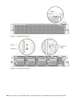
Page 102: ...Figure 41 Front LEDs with bezel on Figure 42 Front LEDs with bezel off 88 Power Systems Installing the System and Ordered Parts for the IBM Power System AC922 8335 GTX...

Page 103: ...35 GTH 8335 GTW or 8335 GTX system that needs servicing Learn how to turn on the blue identify LED to help you find the system that needs servicing Procedure To activate the blue system identify LED u...

Page 104: ...does not increase or decrease your risk of receiving electric shock when using or working on electrical equipment If you do not have an ESD wrist strap just prior to removing the product from ESD pack...

Page 105: ...or or or or Installing and configuring the 8335 GTX 91...

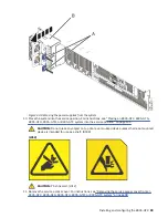
Page 106: ...9 Remove the power supplies from the system as shown in Figure 44 on page 93 a To release a power supply from its position in the system pull the locking tab A to the left b Grasp the power supply ha...

Page 107: ...ervice position on page 101 CAUTION Do not place any object on top of a rack mounted device unless that rack mounted device is intended for use as a shelf R008 L012 CAUTION Pinch hazard L012 11 Remove...

Page 108: ...r on an 8335 GTC 8335 GTG 8335 GTH 8335 GTW or 8335 GTX system on page 99 3 Place the system into the operating position For instructions see Placing an 8335 GTC 8335 GTG 8335 GTH 8335 GTW or 8335 GTX...

Page 109: ...Configure the BMC IP address For instructions see Configuring the BMC IP address www ibm com support knowledgecenter POWER9 p9eih p9eih_configuring_bmc_ip htm 10 Enter the network settings that you r...

Page 110: ...the system or you can use a console to power on the system Procedure 1 Open the front rack door if necessary 2 Before you press the power button ensure that the power supplies are connected to the sys...

Page 111: ...can check the sensor status to quickly determine the general health of the system without using the event codes To view the sensor status use the following command openbmctool U username P password H...

Page 112: ...ervice access cover complete the steps in this procedure Procedure 1 Ensure that you removed both power supplies from the system For instructions see Preparing the 8335 GTC 8335 GTG 8335 GTH 8335 GTW...

Page 113: ...or 8335 GTX system To replace the service access cover complete the steps in this procedure About this task Attention For safety airflow purposes and thermal performance the service access cover must...

Page 114: ...2 Ensure that you have the electrostatic discharge ESD wrist strap on and that the ESD clip is plugged into a ground jack or connected to an unpainted metal surface If not do so now 3 If applicable re...

Page 115: ...GTX system into the service or operating position Placing an 8335 GTC 8335 GTG 8335 GTH 8335 GTW or 8335 GTX system into the service position To place a system into the service position complete the...

Page 116: ...e rack Note When you place the system into the service position you must ensure that all stability plates are firmly installed to prevent the rack from toppling Ensure that only one system unit is rem...

Page 117: ...the left side of the system and one person on the right side of the system 6 Tilt and lift the system from the rails 7 Carefully set the system on a table with an appropriate ESD surface Placing an 8...

Page 118: ...ocedure 1 Unlock the blue rail safety latches A by lifting them upward 2 Align the system unit on to the rails and push the system unit back into the rack until both release latches lock into position...

Page 119: ...f the system 2 Lift the system 3 Tilt the system into position over the fixed rack rails 4 Carefully lower the system until the rear of the system rests on the rails 5 While one person is supporting t...

Page 120: ...35 GTW or 8335 GTX system To disconnect a power cord complete the steps in this procedure Procedure 1 Open the rear rack door on the system unit that you are servicing 2 Identify the system unit that...

Page 121: ...Figure 54 Routing the power cord loop in the cable management arm Installing and configuring the 8335 GTX 107...

Page 122: ...6 on page 109 Note This system might be equipped with two or more power supplies If the removing and replacing procedures require the power to be off then ensure that all the power sources to the syst...

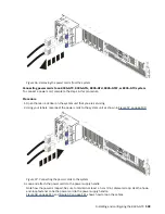
Page 123: ...r labels reconnect the power cords to the system unit as shown in Figure 57 on page 109 Figure 57 Connecting the power cords to the system 3 Loop and attach the power cords to the power supply handle...

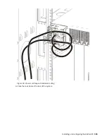
Page 124: ...Figure 58 Routing the power cord loop in the cable management arm 110 Power Systems Installing the System and Ordered Parts for the IBM Power System AC922 8335 GTX...

Page 125: ...Figure 59 Power cord loop with sidewall routing 4 Close the rack door at the rear of the system Installing and configuring the 8335 GTX 111...

Page 126: ...112 Power Systems Installing the System and Ordered Parts for the IBM Power System AC922 8335 GTX...

Page 127: ...ct s and or the program s described in this publication at any time without notice Any references in this information to non IBM websites are provided for convenience only and do not in any manner ser...

Page 128: ...ology content successfully Overview The IBM Power Systems servers include the following major accessibility features Keyboard only operation Operations that use a screen reader The IBM Power Systems s...

Page 129: ...rovide you as the customer the ability to collect personally identifiable information from end users via cookies and other technologies you should seek your own legal advice about any laws applicable...

Page 130: ...linie 2014 30 EU zur Angleichung der Rechtsvorschriften ber die elektromagnetische Vertr glichkeit in den EU Mitgliedsstaatenund h lt die Grenzwerte der EN 55022 EN 55032 Klasse A ein Um dieses sicher...

Page 131: ...elle Informationen Das Ger t erf llt die Schutzanforderungen nach EN 55024 und EN 55022 EN 55032 Klasse A Japan Electronics and Information Technology Industries Association JEITA Notice This statemen...

Page 132: ...energy and if not installed and used in accordance with the instruction manual may cause harmful interference to radio communications Operation of this equipment in a residential area is likely to cau...

Page 133: ...luding the fitting of non IBM option cards German Notice Deutschsprachiger EU Hinweis Hinweis f r Ger te der Klasse B EU Richtlinie zur Elektromagnetischen Vertr glichkeit Dieses Produkt entspricht de...

Page 134: ...en nach EN 55024 und EN 55032 Klasse B Japan Electronics and Information Technology Industries Association JEITA Notice This statement applies to products less than or equal to 20 A per phase This sta...

Page 135: ...or television interference caused by using other than recommended cables and connectors or by unauthorized changes or modifications to this equipment Unauthorized changes or modifications could void...

Page 136: ...e above instructions are not being properly followed You may not download export or re export this information except in full compliance with all applicable laws and regulations including all United S...

Page 137: ......

Page 138: ...IBM...

Reviews: