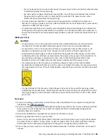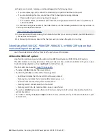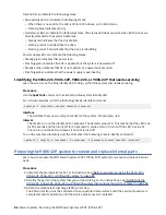
Drive LEDs can indicate the following states:
• Blue activity LED can indicate the following states:
– When there is no activity, the LED is off for SATA drives; on for SAS drives.
– Flashing blue indicates activity
• Red status LED can indicate the following states. The status LED does not work when SATA drives are
directly attached to the system backplane.
– Steady red indicates that the drive failed
– Flashing red at 4 Hz identifies the drive
– Flashing red at 1 Hz indicates that the drive is rebuilding
Power supply LEDs can indicate the following states:
• Steady green indicates that power is on
• Flashing green indicates that AC is applied, but the system is powered off.
• Steady amber indicates that AC is not applied, or a power fault occurred
• Flashing amber indicates that the power supply is overheating
Identifying the 5104-22C, 9006-12P, 9006-22C, or 9006-22P that needs servicing
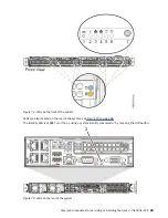
Learn how to turn on the blue identify LED to help you find the system that needs servicing.
Procedure
Use the
ipmitool
command to activate the blue system identify LED.
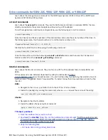
For in-band networks, enter the following chassis identify command:
ipmitool -I <interface> chassis identify <interval>
interface
The interface that you are using to connect to the system. For example,
usb
.
interval
The time to turn on the identify LED in seconds. The default value is 15. This means that the LED is on
for 15 seconds and then turns off for 15 seconds. A value of zero (0) turns off the LED. A value of
force
turns on the LED and leaves it on until turned off.
To run the command remotely over the LAN, enter the following chassis identify command:
ipmitool -I lanplus -H <hostname> -U <username> -P <password> chassis identify <interval>
Preparing the 9006-12P system to remove and replace internal parts
Learn how to prepare the IBM Power System LC921 (9006-12P) system to remove and replace internal
parts.
Procedure
1. Complete the prerequisite tasks. For instructions, see “Before you begin servicing the 5104-22C,
9006-12P, 9006-22C, or 9006-22P system” on page 81.
2. Identify the part and the system that you will be working on. For instructions, see “Identifying the
5104-22C, 9006-12P, 9006-22C, or 9006-22P system that contains the part to replace” on page 84.
3. Attach the electrostatic discharge (ESD) wrist strap.
The ESD wrist strap must be connected to an unpainted metal surface until the service procedure is
completed, and if applicable, until the service access cover is replaced.
86 Power Systems: Servicing the IBM Power System LC921 (9006-12P)
Summary of Contents for Power System LC921 9006-12P
Page 1: ...Power Systems Servicing the IBM Power System LC921 9006 12P IBM...
Page 14: ...xiv Power Systems Servicing the IBM Power System LC921 9006 12P...
Page 118: ...104 Power Systems Servicing the IBM Power System LC921 9006 12P...
Page 120: ...106 Power Systems Servicing the IBM Power System LC921 9006 12P...
Page 131: ......
Page 132: ...IBM...

