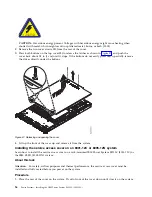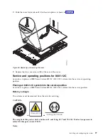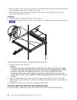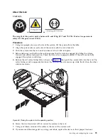
To take the device offline so that it can be removed:
sh -c"echo 0 >/sys/block/nvmeX/device/delete"
Sensor readings GUI display
The sensor readings GUI display is a way to quickly determine the general health status of the server
without having to look at the detailed system event log (SEL) information.
To view the sensor readings GUI display, log in to the BMC web interface. Click Server Health > Sensor
Readings
.
Some occurrences of errors in the system might not appear in the sensor readings GUI. After you view
the sensor readings GUI display, use the SEL logs to view any active SEL events that indicate a service
action event.
Sensor readings display operation
Most sensors are initially gray, then change status and color during the boot process when the FRU is
initialized and either determined to be good (green) or faulty (red). No sensor display is available until
you can get to the sensor display selection on the BMC, which means that the system attains a certain
power level or that the BMC finishes initializing. The indicator color of the sensor is determined based on
the sensor status at time of invocation of the display. The sensor display maintains the sensor status
indicator color until the display is refreshed, which updates the sensor value with the latest status.
Changes to SEL events changes color of sensor indicator when you refresh or restart the display. Sensor
status display also starts over with a reboot or a power cycle.
Sensor status indicator descriptions
Gray indicator:
v
FRU not plugged
v
Sensor not initialized
v
Sensor function is not initialized
Red (faulty) indicator:
v
Critical threshold exceeded (an event requires a service action)
v
Service action required for hard fail
v
Partial function failure that reached a “service action required” state
v
A deconfigured resource requires a service action
Green (good) indicator:
v
FRU or sensor is plugged in and fully operational
v
Recoverable event is below the critical “service action required” threshold
v
FRU or sensor returned to “normal” operating range (for threshold sensors)
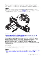
Removing and replacing a power supply in the 8001-12C, 8001-22C,
8005-12N, or 8005-22N
Learn how to remove and replace power supplies in the IBM Power System S821LC (8001-12C), the IBM
Power System S822LC for Big Data (8001-22C), the IBM CS821 (8005-12N), or the IBM CS822 (8005-22N)
systems.
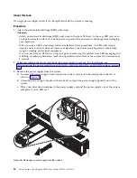
Removing a power supply from the 8001-12C, 8001-22C, 8005-12N, or 8005-22N
Learn how to remove power supplies in the IBM Power System S821LC (8001-12C), the IBM Power
System S822LC for Big Data (8001-22C), the IBM CS821 (8005-12N), or the IBM CS822 (8005-22N) systems.
Installing and configuring the system
93
Summary of Contents for Power System S821LC
Page 1: ...Power Systems Installing the IBM Power System S821LC 8001 12C IBM...
Page 2: ......
Page 3: ...Power Systems Installing the IBM Power System S821LC 8001 12C IBM...
Page 16: ...xiv Power Systems Installing the IBM Power System S821LC 8001 12C...
Page 117: ...Figure 62 Connecting the power cords to the system Installing and configuring the system 101...
Page 118: ...102 Power Systems Installing the IBM Power System S821LC 8001 12C...
Page 130: ...114 Power Systems Installing the IBM Power System S821LC 8001 12C...
Page 131: ......
Page 132: ...IBM Printed in USA...

