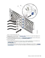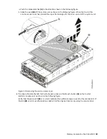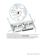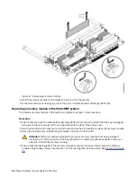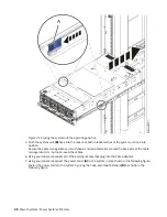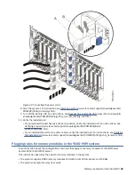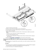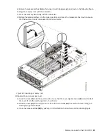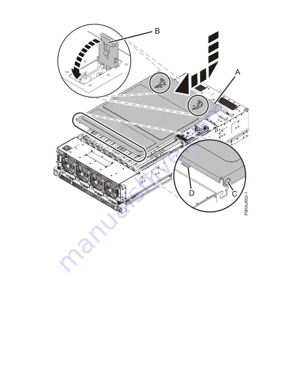
Figure 20. Installing the service access cover
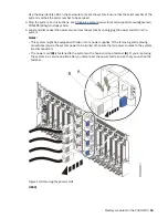
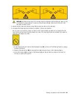
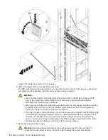
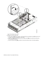
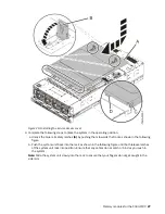
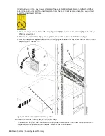
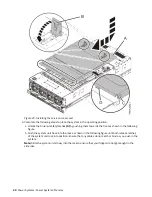
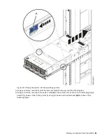
4. Complete the following steps to place the system in the operating position.
a. Unlock the blue rail safety latches (A) by pushing them towards the front as shown in the following
figure.
b. Push the system unit back into the rack as shown in the following figure until both release latches
of the system unit lock into position. Ensure that any cables do not catch or bind as you push in
the system.
Note: Slide the system unit slowly into the rack to ensure that your fingers do not get caught in the
side rails.
Memory modules for the 9040-MR9 27
Summary of Contents for Power System System E950
Page 1: ...Power Systems Memory modules for the 9040 MR9 IBM...
Page 4: ...iv...
Page 14: ...xiv Power Systems Power Systems Memory...
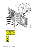
Page 17: ...Figure 1 Removing the power cords L003 or or Memory modules for the 9040 MR9 3...
Page 30: ...or or or or 16 Power Systems Power Systems Memory...
Page 46: ...Figure 23 Removing the power cords L003 or or 32 Power Systems Power Systems Memory...
Page 59: ...Figure 32 Removing the power cords L003 or or Memory riser for the 9040 MR9 45...
Page 70: ...Figure 40 Removing the power cords L003 or or 56 Power Systems Power Systems Memory...
Page 86: ...or or or or 72 Power Systems Power Systems Memory...
Page 105: ......
Page 106: ...IBM...

