background image

For instructions, see Verifying that the hot-plug tools are installed for Linux (http://www.ibm.com/

support/knowledgecenter/POWER9/p9hak/pxhak_linuxhotplugverify.htm).

c) Ensure that you have the POWER

®

 Linux Service Aids installed on your system.

These service aids enable system serviceability, as well to improve system management. If you

are using a Linux distribution with Linux kernel version 2.6 or later, you can install the Service Aids

that give you access to more capabilities, which can help you diagnose problems on your system.

This software is available at the Service and productivity tools for Linux on POWER website (http://

www14.software.ibm.com/webapp/set2/sas/f/lopdiags/home.html).

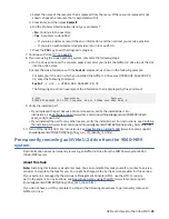
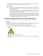
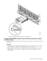
d) Take the NVMe U.2 drive offline before you remove and replace an NVMe U.2 drive when the

system power is turned on.
Before you take an NVMe U.2 drive offline, the devices that are attached to the adapter must

be taken offline as well. This action must be done by a system administrator. Taking the NVMe

U.2 drive offline prevents a service representative or user from causing an unexpected outage for

other users of the system.

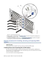
e) Before you hot-plug an NVMe U.2 drive for storage devices, ensure that the file systems on those

devices are unmounted.

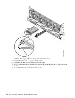
f) Activate the identify function. For instructions, see Identifying a part (www.ibm.com/support/

knowledgecenter/POWER9/p9haj/sal.htm).

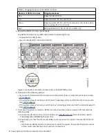
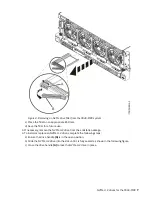
g) Physically verify that the slot you identified is where you want to install or replace the NVMe U.2

drive.
• Use the blue identify LED on the enclosure to locate the system. Ensure that the serial number

of the system matches the serial number to be serviced.

• Look for a flashing amber LED, which identifies the slot that was selected by using the identify

function.

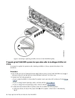
h) To prepare the slot to remove an NVMe U.2 drive by using the Linux operating system, complete

the following steps:

i) Type the following command:

drmgr -c pci -r -s locationcode

Where 

locationcode

 is the location of the slot. For example, the location might be

U78D4.001.AAAXXXX-P2-C1.

ii) Follow the instructions on the display to complete the task.

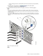
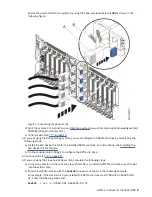
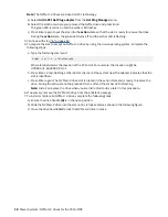
11. Attach the electrostatic discharge (ESD) wrist strap.

The ESD wrist strap must be connected to an unpainted metal surface until the service procedure is

completed, and if applicable, until the service access cover is replaced.
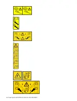
Attention:
• Attach an electrostatic discharge (ESD) wrist strap to the front ESD jack, to the rear ESD jack,

or to an unpainted metal surface of your hardware to prevent the electrostatic discharge

from damaging your hardware.

• When you use an ESD wrist strap, follow all electrical safety procedures. An ESD wrist strap

is used for static control. It does not increase or decrease your risk of receiving electric

shock when using or working on electrical equipment.

• If you do not have an ESD wrist strap, just prior to removing the product from ESD packaging

and installing or replacing hardware, touch an unpainted metal surface of the system for

a minimum of 5 seconds. If at any point in this service process you move away from the

system, it is important to again discharge yourself by touching an unpainted metal surface

for at least 5 seconds before you continue with the service process.

NVMe U.2 drives for the 9040-MR9  15

Summary of Contents for Power System System E950

Page 1: ...Power Systems NVMe U 2 drives for the 9040 MR9 IBM...

Page 2: ...G229 9054 and the IBM Environmental Notices and User Guide Z125 5823 This edition applies to IBM Power Systems servers that contain the POWER9 processor and to all associated models Copyright Interna...

Page 3: ...drive 17 Preparing the system for operation 19 Permanently removing an NVMe U 2 drive 21 Preparing the system 22 Permanently removing an NVMe U 2 drive 25 Preparing the system for operation 27 Relate...

Page 4: ...iv...

Page 5: ...rdnung geeignet Laser safety information IBM servers can use I O cards or features that are fiber optic based and that utilize lasers or LEDs Laser compliance IBM servers may be installed inside or ou...

Page 6: ...AC power attach the power cords to the outlets 5 For racks with a DC power distribution panel PDP restore the power from the Customer s DC power source and turn on the circuit breakers located in the...

Page 7: ...mpromise the supply wiring or overcurrent protection To provide the correct power connection to a rack refer to the rating labels located on the equipment in the rack to determine the total power requ...

Page 8: ...cation complete the following steps Lower the four leveling pads Install stabilizer brackets on the rack cabinet or in an earthquake environment bolt the rack to the floor If you removed any devices f...

Page 9: ...not put any load on the slide rail mounted equipment mounted in the installation position Do not leave the slide rail mounted equipment in the installation position L002 L003 or or or or Safety notice...

Page 10: ...as a class 1 laser product Consult the label on each part for laser certification numbers and approval information CAUTION This product might contain one or more of the following devices CD ROM drive...

Page 11: ...d for use to assist lift install remove units load up into rack elevations It is not to be used loaded transporting over major ramps nor as a replacement for such designated tools like pallet jacks wa...

Page 12: ...inch handle A winch accident could cause serious injury Not for moving humans Make certain clicking sound is heard as the equipment is being raised Be sure winch is locked in position before releasing...

Page 13: ...d DC return DC I design The DC battery return terminal shall not be connected to the chassis or frame ground The dc powered system is intended to be installed in a common bonding network CBN as descri...

Page 14: ...xiv Power Systems NVMe U 2 drives for the 9040 MR9...

Page 15: ...art in the system For instructions see Installing a part by using the HMC www ibm com support knowledgecenter POWER9 p9haj hmcinstall htm If you do not have an HMC complete the steps in these procedur...

Page 16: ...em power is turned off continue with step 7 on page 2 If the system power is turned on and if the AIX operating system controls the slot continue with step 10 on page 5 If the system power is turned o...

Page 17: ...following figure Notes This system might be equipped with two or more power supplies If the removing and replacing procedures require the system power to be turned off ensure that all power sources to...

Page 18: ...or or or or 4 Power Systems NVMe U 2 drives for the 9040 MR9...

Page 19: ...s identified flashes f Physically verify that the slot you identified is where you want to install or replace the NVMe U 2 drive Use the blue identify LED on the enclosure to locate the system Ensure...

Page 20: ...s replaced Attention Attach an electrostatic discharge ESD wrist strap to the front ESD jack to the rear ESD jack or to an unpainted metal surface of your hardware to prevent the electrostatic dischar...

Page 21: ...the NVMe U 2 drive from the antistatic package 4 To install or replace an NVMe U 2 drive complete the following steps a Ensure the drive handle A is in the open position b Slide the NVMe U 2 drive int...

Page 22: ...d jack or connected to an unpainted metal surface If not do so now 2 Choose from the following options If you installed an NVMe U 2 drive when the system power was turned off continue with step 3 on p...

Page 23: ...alled NVMe U 2 drive For instructions see Installing the AIX device driver software b On the console enter cfgmgr to configure the NVMe U 2 drive 5 Continue with step 7 on page 10 6 If you are using t...

Page 24: ...m support knowledgecenter POWER9 p9haj p9haj_turn_off_identify_led htm Removing and replacing an NVMe U 2 drive in the 9040 MR9 system Find information about removing and replacing an NVMe U 2 drive i...

Page 25: ...NVMe U 2 drive Use the blue identify LED on the enclosure to locate the system Ensure that the serial number of the system matches the serial number to be serviced Look for a flashing amber LED which...

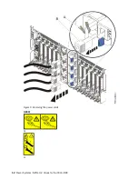
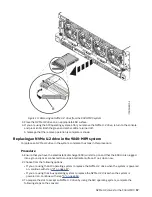
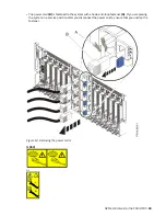
Page 26: ...Figure 9 Removing the power cords L003 or or 12 Power Systems NVMe U 2 drives for the 9040 MR9...

Page 27: ...product might be equipped with multiple AC power cords or multiple DC power cables To remove all hazardous voltages disconnect all power cords and power cables L003 8 Continue with step 11 on page 15...

Page 28: ...er No to Keep Definition Then use the Tab key again to answer Yes to Unconfigure Child Devices and then press Enter Press Enter to confirm the operation The OK message next to the Command field confir...

Page 29: ...enclosure to locate the system Ensure that the serial number of the system matches the serial number to be serviced Look for a flashing amber LED which identifies the slot that was selected by using t...

Page 30: ...into a ground jack or connected to an unpainted metal surface If not do so now 2 To remove an NVMe U 2 drive from the system complete the following steps a Press the release latch A in the direction t...

Page 31: ...ure Procedure 1 Ensure that you have the electrostatic discharge ESD wrist strap on and that the ESD clip is plugged into a ground jack or connected to an unpainted metal surface If not do so now 2 Ch...

Page 32: ...he PCIe slot For example the location might be U78D4 001 AAAXXXX P2 C1 b Press Enter A fast flashing amber LED at the rear of the system near the adapter indicates that the slot is identified c Press...

Page 33: ...is plugged into a ground jack or connected to an unpainted metal surface If not do so now 2 Choose from the following options If the system power is turned off continue with step 3 on page 19 If you...

Page 34: ...on list b Select Log Repair Action c Select the resource that you replaced and select Commit d Press F3 to return to Task Selection List e Select Hot Plug Task PCI Hot Plug Manager Configure a defined...

Page 35: ...0 01 0 9 Verify the installed part If you replaced the part because of a service action verify the installed part For instructions see Verifying a repair www ibm com support knowledgecenter POWER9 p9e...

Page 36: ...bm com support knowledgecenter POWER9 p9haj sal htm b Physically verify that the slot you identified is where you want to install or replace the NVMe U 2 drive Use the blue identify LED on the enclosu...

Page 37: ...tem with a hook and loop fastener A If you are placing the system in a service position after you disconnect the power cords ensure that you unstrap the fastener Figure 14 Removing the power cords L00...

Page 38: ...be equipped with multiple AC power cords or multiple DC power cables To remove all hazardous voltages disconnect all power cords and power cables L003 5 Attach the electrostatic discharge ESD wrist s...

Page 39: ...al surface of the system for a minimum of 5 seconds If at any point in this service process you move away from the system it is important to again discharge yourself by touching an unpainted metal sur...

Page 40: ...ate ESD surface 4 To insure proper airflow you must install a NVMe drive filler a With the NVMe drive filler handle A in the open position slide the filler into the slot until it is fully seated b Clo...

Page 41: ...in this procedure Procedure 1 Ensure that you have the electrostatic discharge ESD wrist strap on and that the ESD clip is plugged into a ground jack or connected to an unpainted metal surface If not...

Page 42: ...r installing removing and replacing NVMe devices About this task Find procedures that are related to installing removing and replacing NVMe devices Checking the amount of remaining life in NVMe device...

Page 43: ...ng an operational NVMe device from an IBM i logical partition on page 29 Learn how to remove an operational NVMe device from an IBM i logical partition Removing an operational NVMe device from an IBM...

Page 44: ...30 Power Systems NVMe U 2 drives for the 9040 MR9...

Page 45: ...ct s and or the program s described in this publication at any time without notice Any references in this information to non IBM websites are provided for convenience only and do not in any manner ser...

Page 46: ...to use information technology content successfully Overview The IBM Power Systems servers include the following major accessibility features Keyboard only operation Operations that use a screen reader...

Page 47: ...personally identifiable information If the configurations deployed for this Software Offering provide you as the customer the ability to collect personally identifiable information from end users via...

Page 48: ...d rfen auch nur von der IBM empfohlene Kabel angeschlossen werden IBM bernimmt keine Verantwortung f r die Einhaltung der Schutzanforderungen wenn das Produkt ohne Zustimmung von IBM ver ndert bzw wen...

Page 49: ...Technology Industries Association JEITA Notice This statement applies to products less than or equal to 20 A per phase This statement applies to products greater than 20 A single phase This statement...

Page 50: ...o cause harmful interference in which case the user will be required to correct the interference at his own expense Properly shielded and grounded cables and connectors must be used in order to meet F...

Page 51: ...tromagnetische Vertr glichkeit in den EU Mitgliedsstaatenund h lt die Grenzwerte der EN 55022 EN 55032 Klasse B ein Um dieses sicherzustellen sind die Ger te wie in den Handb chern beschrieben zu inst...

Page 52: ...mation Technology Industries Association JEITA Notice This statement applies to products less than or equal to 20 A per phase This statement applies to products greater than 20 A single phase This sta...

Page 53: ...r modifications to this equipment Unauthorized changes or modifications could void the user s authority to operate the equipment This device complies with Part 15 of the FCC rules Operation is subject...

Page 54: ...this information except in full compliance with all applicable laws and regulations including all United States export laws and regulations IBM MAKES NO GUARANTEE ABOUT THE CONTENT OF THESE PUBLICATI...

Page 55: ......

Page 56: ...IBM...

Reviews: