background image

p8eab_mtm_pciplacement.htm) and select the system you are working on.

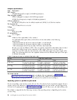
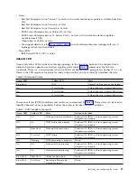
Operating system or partition requirements

The adapter is supported on the following versions of the operating systems, depending on the system
you are using:

v

AIX
– AIX 7.1, Technology Level 3, Service Pack 2, or later
– AIX 6.1, Technology Level 8, Service Pack 3, or later
– AIX Version 5.3, Technology Level 12, or later

v

Linux
– Red Hat Enterprise Linux Version 7, or later, with current maintenance updates available from Red

Hat.

– Red Hat Enterprise Linux Version 6.4, or later, with current maintenance updates available from Red

Hat.

– SUSE Linux Enterprise Server Version 12, or later
– SUSE Linux Enterprise Server 11, Service Pack 2, or later, with current maintenance updates

available from SUSE.

– Ubuntu Server 14.04.3, or later
– For support details, see the Linux Alert website (www14.software.ibm.com/webapp/set2/sas/f/

lopdiags/info/LinuxAlerts.html).

– The latest version of the device driver or iprutils can be downloaded from IBM Service and

Productivity Tools website (http://www14.software.ibm.com/webapp/set2/sas/f/lopdiags/
home.html).

v

IBM i
– IBM i Version 7.2 or later
– IBM i Version 7.1, or later

v

VIOS
– VIOS support requires VIOS 2.2.1.4, or later.

v

PowerKVM
– IBM PowerKVM 2.1.1, or later

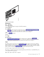
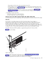
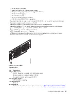
PCIe3 LP 2-Port 40 GbE NIC RoCE QSFP+ Adapter (FC EC3A; CCIN 57BD)

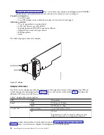
Learn about the specifications and operating system requirements for the feature code (FC) EC3A adapter.

Overview

The PCIe3 LP 2-Port 40 GbE NIC RoCE QSFP+ Adapter is a low-profile, PCIe generation-3 (PCIe3), dual
port, 40-Gigabit Ethernet (GbE) adapter with a PCIe 3.0 host bus interface. The adapter acts as a network
interface controller (NIC) and uses the IBTA RDMA over Converged Ethernet (RoCE) protocols to provide
efficient Remote Direct Memory Access (RDMA) services. The adapter delivers high-bandwidth and
low-latency 40 GbE connectivity, reducing the load on the processor and efficiently using the memory
access. This action off-loads the processor from networking tasks which improves the performance and
scalability of the processor.

The adapter is optimized for enterprise data centers, high-performance computing, transaction databases,
cloud computing, virtualization, storage, and other embedded environments. The adapter improves
network performance by increasing available bandwidth to the processor and by providing enhanced
performance. The adapter provides dedicated adapter resources and protection for virtual machines (VM).
The link aggregation and failover features of the adapter are ideal for critical network applications that
require redundancy and high availability.

Installing and configuring the system

35

Summary of Contents for Power Systems S812LC 8348-21C

Page 1: ...Power Systems Installing the System and Ordered Parts for the IBM Power System S812LC 8348 21C IBM...

Page 2: ......

Page 3: ...Power Systems Installing the System and Ordered Parts for the IBM Power System S812LC 8348 21C IBM...

Page 4: ...y Notices manual G229 9054 and the IBM Environmental Notices and User Guide Z125 5823 This edition applies to IBM Power Systems servers that contain the POWER8 processor and to all associated models C...

Page 5: ...ID adapter FC EC3Y PMC 71605E 42 PCIe LP 8 Gb 2 Port Fibre Channel Adapter FC EL2N CCIN 577D 45 PCIe2 LP 2 port 10 GbE BaseT RJ45 Adapter FC EL3Z CCIN 2CC4 48 PCIe2 LP 4 Port 10Gb 1GbE SR RJ45 Adapter...

Page 6: ...iv Installing the System and Ordered Parts for the 8348 21C...

Page 7: ...oduct The documentation contains the safety information in your national language with references to the U S English source Before using a U S English publication to install operate or service this pr...

Page 8: ...tch on power to the machine until all possible unsafe conditions are corrected v Assume that an electrical safety hazard is present Perform all continuity grounding and power checks specified during t...

Page 9: ...e customer to ensure that the outlet is correctly wired and grounded to prevent an electrical shock CAUTION v Do not install a unit in a rack where the internal rack ambient temperatures will exceed t...

Page 10: ...te potential hazards v Verify that the route that you choose can support the weight of the loaded rack cabinet Refer to the documentation that comes with your rack cabinet for the weight of a loaded r...

Page 11: ...DANGER Rack mounted devices are not to be used as shelves or work spaces L002 L003 or or 1 2 3 4 or Safety notices ix...

Page 12: ...r cords The product might be equipped with multiple power cords To remove all hazardous voltages disconnect all power cords L003 L007 CAUTION A hot surface nearby L007 L008 x Installing the System and...

Page 13: ...tacle Although shining light into one end and looking into the other end of a disconnected optical fiber to verify the continuity of optic fibers many not injure the eye this procedure is potentially...

Page 14: ...or lean Keep riser tilt option flat at all times except for final minor adjustment when needed v Do not stand under overhanging load v Do not use on uneven surface incline or decline major ramps v Do...

Page 15: ...interfaces that connect to the OSP outside plant or its wiring These interfaces are designed for use as intrabuilding interfaces only Type 2 or Type 4 ports as described in GR 1089 CORE and require i...

Page 16: ...xiv Installing the System and Ordered Parts for the 8348 21C...

Page 17: ...This bulletin provides a list of the key IBM system installation activities and a list of activities that might be billable Installing the IBM Power System S812LC 8348 21C system Learn how to install...

Page 18: ...on to view the service and support contact information Determining and marking the location in the rack for the 8348 21C system You might need to determine where to install the system unit into the ra...

Page 19: ...3 If necessary remove the filler panels to allow access to the inside of the rack enclosure where you plan to place the unit as shown in Figure 1 on page 4 Installing and configuring the system 3...

Page 20: ...rear of the rack 8 On the right side find the EIA unit that corresponds to the bottom EIA unit marked on the front of the rack 9 Mark the bottom EIA unit 10 Mark the corresponding holes on the left s...

Page 21: ...The slide rails arrive fully assembled To install the slide rails into the rack you must disassemble the slide rails into four pieces Procedure 1 Remove the lower DASD backplane screw on either side...

Page 22: ...ring it to the front of the rack and locate the selected EIA unit 5 From the front of the rack insert the pins on the front of the slide rail 1 into the holes on the front of the rack that you previou...

Page 23: ...he rack Pull the slide rail toward you to insert the two pins 1 into the rack holes 2 Pull the rail until the rail spring clip 3 clicks into place Install the screw 4 to secure the slide rail to the r...

Page 24: ...o install the system into the rack Procedure 1 Fully extend the slide rails until the rails click into the service position A 2 Using two people lift the system and align the lower roller pins on the...

Page 25: ...ting and routing power cables Learn how to connect and route power cables in the IBM Power System S812LC 8348 21C system Procedure 1 To connect the power cables complete the following steps a Plug the...

Page 26: ...is supported 2 Go to Getting fixes http www ibm com support knowledgecenter POWER8 p8ei8 p8ei8_fixes_kickoff htm and update the system firmware with the most recent level of firmware 3 You can receive...

Page 27: ...is powered on and running Procedure 1 Attach the electrostatic discharge ESD wrist strap Attention v Attach an electrostatic discharge ESD wrist strap to an unpainted metal surface of your hardware t...

Page 28: ...tional drive trays 5 Install a drive into the tray Orient the drive such that the connectors are pointing to the rear of the drive v A 3 5 inch drive fills the tray as shown in Figure 10 on page 13 Fa...

Page 29: ...e 11 6 Hold the drive tray by the bottom as you position the drive tray Slide the drive try all the way into the system Push the drive tray in until the drive tray handle A starts to close then push t...

Page 30: ...rescan scsi bus a This tool is provided in the sg3_utils package which can be installed by using the command yum install sg3_utils b Load or restore data from your backup media If a drive failed refer...

Page 31: ...ging and installing or replacing hardware touch an unpainted metal surface of the system for a minimum of 5 seconds 3 Unlock the rear drive tray handle by pushing in the handle release A The handle th...

Page 32: ...drive to the sides of the tray by using four screws 2 on each side as shown in Figure 15 on page 17 Figure 14 Installing the 3 5 inch drive into the tray 16 Installing the System and Ordered Parts for...

Page 33: ...the socket as shown in Figure 16 b While you hold both the drive and the tray turn the tray over such that the drive is facing down Figure 15 Fastening the 3 5 inch drive to the tray Figure 16 Instal...

Page 34: ...ld the drive tray by the bottom as you position the drive Slide the drive tray all the way into the system Push the drive tray in until the handle starts to close then push the handle in until it lock...

Page 35: ...he command rescan scsi bus a This tool is provided in the sg3_utils package which can be installed by using the command yum install sg3_utils b Load or restore data from your backup media If a drive f...

Page 36: ...antity of the memory feature code that can be ordered which corresponds to the DIMM size in the leftmost column 32 GB 64 GB 128 GB 256 GB 512 GB 1024 GB DIMM Size DIMMs DIMMs DIMMs DIMMs DIMMs DIMMs 4...

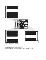
Page 37: ...Installing memory in the 8348 21C Learn how to install memory in the IBM Power System S812LC 8348 21C system Figure 19 8348 21C memory slot locations Installing and configuring the system 21...

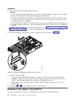
Page 38: ...lacement rules for memory in the 8348 21C system on page 19 to understand the plugging rules and ensure that the memory are plugged in the correct sequence 3 Push the locking tabs away from the socket...

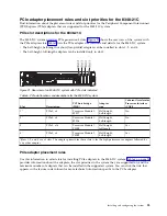
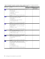
Page 39: ...ent Accelerator Processor Interface CAPI 11 PCIe3 x8 Processor Module 1 S2P17 Half height half length No 21 PCIe3 x8 Processor Module 1 S2P16 Half height half length No 3 PCIe3 x16 Processor Module 1...

Page 40: ...12 Gbs low profile short form factor FC EC3S Adapter FRU number 00WV555 v Supported RAID levels 0 1 1E 5 6 10 50 60 and Hybrid RAID 1 and 10 v Cache memory 1024 MB OS support Red Hat Linux Ubuntu and...

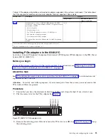
Page 41: ...m to 3 Installing PCIe adapters in the 8348 21C Learn how to install Peripheral Component Interconnect PCI Express PCIe adapters in the IBM Power System S812LC 8348 21C Before you begin Power off the...

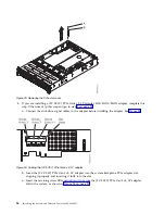
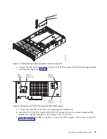
Page 42: ...e 24 b Insert the FC EC3Y PCIe Gen3 x8 LP adapter into the system backplane PCIe adapter slot aligning it properly and inserting it fully into the slot c Insert the retaining screw B and tighten it to...

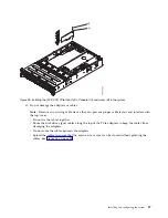
Page 43: ...rive signal cables along the top of the PCIe adapters to keep the cables from damaging the adapters v Do not route the cables between the adapters v Spread the cables to ensure that the service access...

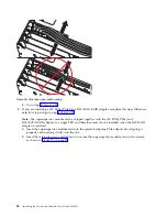
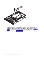
Page 44: ...as a single FRU and therefore must also be installed when the SAS RAID adapter is installed a Insert the supercapacitor module card into the system backplane PCIe adapter slot aligning it properly an...

Page 45: ...CIe Gen3 SAS SATA RAID adapter A into the system backplane PCIe adapter slot aligning it properly and inserting it fully into the slot f Insert the retaining screw B and tighten it to secure the PCIe...

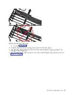
Page 46: ...can be closed without pinching the cables See Figure 30 on page 31 for an example of how to route the cables along the top of the PCIe adapters Your cable connections may differ from Figure 30 on page...

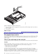
Page 47: ...Ie adapter A into the PCIe slot in the system backplane aligning it properly and inserting it fully into the slot 8 Insert the retaining screw B and tighten it to secure the PCIe adapter in the system...

Page 48: ...tions and operating system requirements for the feature code FC 5260 adapters Overview FC 5260 and FC 5899 are both the same adapter with different feature codes FC 5260 is a low profile adapter and t...

Page 49: ...el GEC with the existing software v Supports IEEE 802 3ad Link Aggregation control protocol v Supports IEEE 802 1Q VLANs v Supports IEEE 802 3 z ab u x flow control support v Supports IEEE 802 1p v Su...

Page 50: ...provide information about the operation status of the adapter The LEDs are visible through the mounting bracket Figure 32 shows the location of the LEDs Table 7 describes the different LED states and...

Page 51: ...VM IBM PowerKVM 2 1 1 or later PCIe3 LP 2 Port 40 GbE NIC RoCE QSFP Adapter FC EC3A CCIN 57BD Learn about the specifications and operating system requirements for the feature code FC EC3A adapter Over...

Page 52: ...CoE v TCP IP stateless offload in hardware v Traffic steering across multiple cores v Hardware based Single root I O virtualization SR IOV capable v Intelligent interrupt coalescence v Advanced Qualit...

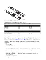
Page 53: ...knowledgecenter POWER8 p8eab p8eab_mtm_pciplacement htm and select the system you are working on Cables This adapter feature requires the use of compatible QSFP 40 Gbps copper twinaxial active Etherne...

Page 54: ...s To check for the prerequisites see IBM Prerequisite website www 912 ibm com e_dir eServerPrereq nsf The adapter is supported on the following versions of the operating systems depending on the syste...

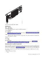
Page 55: ...ection of the write cache in case of power loss Note The adapter can connect to the 12 internal front disk bays on the 8348 21C SATA devices are supported at up to 6 Gb s per port For details about sl...

Page 56: ...res If you do not install the maxView Storage Manager utility you need to use manual tools such as the ARCCONF command line utility ARCCONF does not offer the automatic monitoring and reporting of iss...

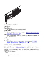
Page 57: ...f adapters that are supported see PCIe adapter placement rules and slot priorities for the 8348 21C on page 23 Operating system or partition requirements If you are installing a new feature ensure tha...

Page 58: ...of which has four x1 ports allowing it to support up to 16 drives The adapter supports RAID 0 1 1E 10 and the hot plug of its attached drives Note Cache content is lost if a problem such as a power fa...

Page 59: ...matic monitoring and reporting of issues such as disk failures The maxView Storage Manager includes the following options Web based GUI Management utility Remote configuration monitoring and notificat...

Page 60: ...that are supported see PCIe adapter placement rules and slot priorities for the 8348 21C on page 23 Operating system or partition requirements If you are installing a new feature ensure that you have...

Page 61: ...is a low profile adapter The PCIe LP 8 Gb 2 Port Fibre Channel Adapter is a high performance adapter based on the Emulex LPe12002 PCIe Host Bus Adapter HBA Each port provides single initiator capabil...

Page 62: ...eds Table 9 Supported distances for multimode fiber optic cables Header Cable Type and Distance Rate OM1 OM2 OM3 2 125 Gbps 0 5 meters to 150 meters 1 64 feet to 492 12 feet 0 5 meters to 300 meters 1...

Page 63: ...r not started On 2 fast flashes 2 Gbps link rate normal link active On 3 fast flashes 4 Gbps link rate normal link active On 4 fast flashes 8 Gbps link rate normal link active Power on self test POST...

Page 64: ...ports This adapter provides a PCIe 2 0 host bus interface The adapter supports the Ethernet network interface controller NIC function The adapter is a high performance adapter that consolidates traffi...

Page 65: ...TCP user datagram protocol UDP TCP segmentation Offload TSO for IPv4 and IPv6 v Supports TCP segmentation or large send offload v Supports EEPROM SPI and single EEPROM v Compliant with European Union...

Page 66: ...or later SUSE Linux Enterprise Server 11 Service Pack 3 or later with current maintenance updates available from SUSE Ubuntu Server 14 04 3 or later For support details see the Linux Alert website ww...

Page 67: ...while significantly reducing processor utilization v The adapter supports dual port operation in any PCIe3 or PCIe2 slot v The adapter supports auto negotiation full duplex only v The adapter supports...

Page 68: ...s and slot priorities http www ibm com support knowledgecenter POWER8 p8eab p8eab_mtm_pciplacement htm and select the system you are working on Cables See Cables on page 53 for details Voltage 3 3 V F...

Page 69: ...e are any prerequisites for this feature and attaching devices To check for the prerequisites see IBM Prerequisite website www 912 ibm com e_dir eServerPrereq nsf The adapter is supported on the follo...

Page 70: ...ou begin Observe these precautions when you are installing removing or replacing features and parts About this task These precautions are intended to create a safe environment to service your system a...

Page 71: ...mpt to switch on power to the machine until all possible unsafe conditions are corrected v Assume that an electrical safety hazard is present Perform all continuity grounding and power checks specifie...

Page 72: ...that the outlet is correctly wired and grounded to prevent an electrical shock CAUTION v Do not install a unit in a rack where the internal rack ambient temperatures will exceed the manufacturer s re...

Page 73: ...rt In the United States the IBM Rochester Manufacturing Automated Information Line R MAIL at 1 800 300 8751 In countries and regions outside of the United States use the following website to locate yo...

Page 74: ...r of the system LAN connectors Power supplies green LED indicates that power is on and functioning properly amber LED indicates a problem with the power supply PCIe adapters Identifying the 8348 21C s...

Page 75: ...o work on For instructions see Identifying the 8348 21C system that needs servicing on page 58 3 If applicable open the rack front door 4 Attach the electrostatic discharge ESD wrist strap Attention v...

Page 76: ...or or 1 2 3 4 or 1 2 3 4 or 60 Installing the System and Ordered Parts for the 8348 21C...

Page 77: ...ee Removing the service access cover from an 8348 21C system on page 67 Preparing the system for operation after removing and replacing internal parts for the 8348 21C Learn how to prepare the IBM Pow...

Page 78: ...o files to a portable USB device v Arcconf 1 0n 21nnn pb plugin v Latest firmware If you have a Series 7 adapter copy EC3Y PMC 71605E as716E01 ufi If you have a Series 8 adapter copy EC3S PMC 81605Z A...

Page 79: ...en the front rack door if necessary 2 Before you press the power button ensure that the power supplies are connected to the system unit and verify the following items v All system power cables are con...

Page 80: ...m unit that you are servicing 2 Identify the system unit that you are servicing in the rack 3 Disconnect the power cords from the power supply handle 4 Label and disconnect the power cords from the sy...

Page 81: ...ensure that all stability plates are firmly installed to prevent the rack from toppling Ensure that only one system unit is in the service position at a time v Ensure that the cables at the rear of th...

Page 82: ...working on the system backplane the recommendation is to remove the system from the rails 7 If you need to remove the system from the rails use a lift tool or seek the help of a second person If a se...

Page 83: ...oper locations For instructions see Replacing a front drive in the 8348 21C on page 78 5 Release the rail safety latches A by lifting them upward as shown in Figure 46 then push the system fully into...

Page 84: ...rack mounted IBM Power System S812LC 8348 21C system About this task Attention For safety airflow purposes and thermal performance the service access cover must be installed and fully seated before y...

Page 85: ...system Learn how to remove the processor baffle from an IBM Power System S812LC 8348 21C system Procedure Remove the processor baffle as shown in Figure 49 on page 70 Figure 48 Replacing the service...

Page 86: ...r baffle in an IBM Power System S812LC 8348 21C system Procedure 1 Route the drive signal cable and drive power cable through the cable slot A in the baffle as shown in Figure 50 on page 71 Figure 49...

Page 87: ...the baffle as shown in Figure 50 3 Carefully press the baffle fully into the system Figure 50 Replacing the processor baffle Route the drive signal cable and drive power cable through A align the air...

Page 88: ...72 Installing the System and Ordered Parts for the 8348 21C...

Page 89: ...rease or decrease your risk of receiving electric shock when using or working on electrical equipment v If you do not have an ESD wrist strap just prior to removing the product from ESD packaging and...

Page 90: ...er System S812LC 8348 21C system Procedure 1 Align the power supply C with the bay and slide the power supply into the system until the latch B locks in place See Figure 52 on page 75 Figure 51 Removi...

Page 91: ...plies and strap them c Loop the power cables For instructions see Connecting the power cords to an 8348 21C system on page 64 What to do next See Preparing the system for operation after removing and...

Page 92: ...ng the device before continuing to step 3 v A raw disk v A member of a simple volume v A member of a raid 0 logical drive 3 Identify device and prepare it for removal a Run the arcconf command to list...

Page 93: ...more than one drive repeat the steps 3 on page 76 to 5 in this procedure until all drives are removed 7 Remove a drive from the tray v For a 3 5 inch drive unfasten the drive from the sides of the tra...

Page 94: ...he 8348 21C Learn how to remove a front drive in the IBM Power System S812LC 8348 21C system Procedure 1 Ensure that you have the electrostatic discharge ESD wrist strap attached If not attach it now...

Page 95: ...o the sides of the tray with four screws 2 on each side v A 2 5 inch drive must be positioned at the rear of the tray While you hold both the drive and the tray turn the tray over Fasten the drive to...

Page 96: ...run the command rescan scsi bus This tool is provided in the scsitools package which can be installed by using the command sudo apt get install scsitools v REHL 7 2 To run the rescan command in Red H...

Page 97: ...herefore this statement may not apply to you This information could include technical inaccuracies or typographical errors Changes are periodically made to the information herein these changes will be...

Page 98: ...oftware Homologation statement This product may not be certified in your country for connection by any means whatsoever to interfaces of public telecommunications networks Further certification may be...

Page 99: ...harmful interference to radio communications Operation of this equipment in a residential area is likely to cause harmful interference in which case the user will be required to correct the interferen...

Page 100: ...ning This is a Class A product In a domestic environment this product may cause radio interference in which case the user may be required to take adequate measures VCCI Statement Japan The following i...

Page 101: ...is product may cause radio interference in which case the user may need to perform practical action Electromagnetic Interference EMI Statement Taiwan The following is a summary of the EMI Taiwan state...

Page 102: ...von Fremdherstellern ohne Empfehlung von IBM gesteckt eingebaut werden EN 55022 Klasse A Ger te m ssen mit folgendem Warnhinweis versehen werden Warnung Dieses ist eine Einrichtung der Klasse A Diese...

Page 103: ...ed to provide reasonable protection against harmful interference in a residential installation This equipment generates uses and can radiate radio frequency energy and if not installed and used in acc...

Page 104: ...ctive 2004 108 EC on the approximation of the laws of the Member States relating to electromagnetic compatibility IBM cannot accept responsibility for any failure to satisfy the protection requirement...

Page 105: ...20 A single phase the following statements apply For products greater than 20 A per phase three phase the following statements apply IBM Taiwan Contact Information Electromagnetic Interference EMI St...

Page 106: ...dem Deutschen Gesetz ber die elektromagnetische Vertr glichkeit von Ger ten EMVG bzw der EMC EG Richtlinie 2004 108 EG f r Ger te der Klasse B Dieses Ger t ist berechtigt in bereinstimmung mit dem De...

Page 107: ...intellectual property contained therein IBM reserves the right to withdraw the permissions granted herein whenever in its discretion the use of the publications is detrimental to its interest or as de...

Page 108: ...92 Installing the System and Ordered Parts for the 8348 21C...

Page 109: ......

Page 110: ...IBM Printed in USA...

Reviews: