
2.
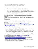
Pull the system unit out of the rack.
3.
If you are working on the front USB and cable, you must remove the system from the rails. You must
also remove the left rail holder to access the mounting screws on the side of the system.
4.
If you are working on the power switch and cable, you must remove the system from the rails. You
must also remove the right rail holder to access the mounting screws on the side of the system.
5.
If you are working on the disk drive backplane, and did not remove the lower side screws during
installation, you must remove the system from the rails. You must also remove both rail holders to
access the lower mounting screws on the side of the system.
If you did remove the lower side screws during installation, you can service the system while it
remains in the rails.
6.
If you are working on the system backplane, the recommendation is to remove the system from the
rails.
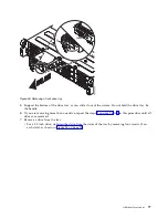
7.
If you need to remove the system from the rails, use a lift tool or seek the help of a second person. If
a second person is not available, you can also make the system lighter by doing the following steps:
a.
Remove the power supplies. For instructions, see “Removing a power supply from the 8348-21C”
on page 73.
b.
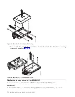
Label and remove the front drives, keeping track of their locations. For instructions, see
“Removing a front drive in the 8348-21C” on page 75.
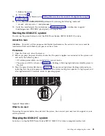
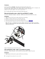
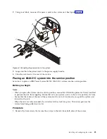
Placing an 8348-21C system into the operating position
Learn how to place an IBM Power System S812LC (8348-21C) system into the operating position.
Before you begin
When you place the system in the operating position, ensure that the cables at the rear of the system do
not catch or bind as you push the system unit back into the rack.
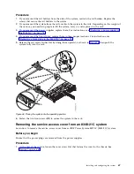
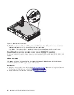
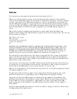
Figure 45. Removing the front screws and removing the system from the rack
66
Installing the System and Ordered Parts for the 8348-21C
Summary of Contents for Power Systems S812LC 8348-21C
Page 2: ......
Page 6: ...iv Installing the System and Ordered Parts for the 8348 21C...
Page 16: ...xiv Installing the System and Ordered Parts for the 8348 21C...
Page 76: ...or or 1 2 3 4 or 1 2 3 4 or 60 Installing the System and Ordered Parts for the 8348 21C...
Page 88: ...72 Installing the System and Ordered Parts for the 8348 21C...
Page 108: ...92 Installing the System and Ordered Parts for the 8348 21C...
Page 109: ......
Page 110: ...IBM Printed in USA...


