Procedure
1.
If you removed the rail holders from the side of the system, reattach the rail holders. Replace the
screws that secure the rail holders to the system.
2.
If you removed the system from the rails, reattach the system to the rails. Depending on the weight of
the system, you need two people to lift the system, carry it, and replace it in the rack.
3.
If you removed the power supplies, replace them. For instructions, see “Replacing a power supply in
the 8348-21C” on page 74.
4.
If you removed the front drives, replace them in their proper locations. For instructions, see
“Replacing a front drive in the 8348-21C” on page 78.
5.
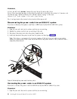
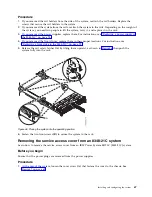
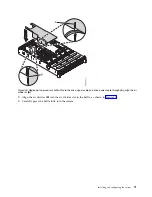
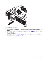
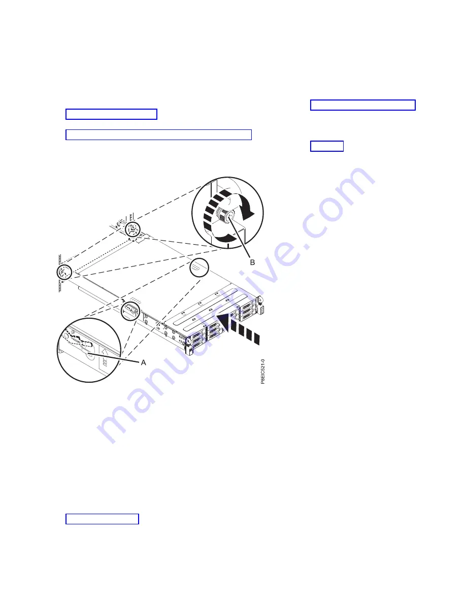
Release the rail safety latches (A) by lifting them upward, as shown in Figure 46, then push the
system fully into the rack.
6.
Fasten the two front screws (B) to secure the system to the rack.
Removing the service access cover from an 8348-21C system
Learn how to remove the service access cover from an IBM Power System S812LC (8348-21C) system.
Before you begin
Ensure that the power plugs are removed from the power supplies.
Procedure
1.
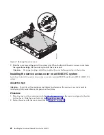
At the rear of the system, loosen the cover screw (A) that fastens the cover to the chassis. See
Figure 47 on page 68.
Figure 46. Placing the system into the operating position
Installing and configuring the system
67
Summary of Contents for Power Systems S812LC 8348-21C
Page 2: ......
Page 6: ...iv Installing the System and Ordered Parts for the 8348 21C...
Page 16: ...xiv Installing the System and Ordered Parts for the 8348 21C...
Page 76: ...or or 1 2 3 4 or 1 2 3 4 or 60 Installing the System and Ordered Parts for the 8348 21C...
Page 88: ...72 Installing the System and Ordered Parts for the 8348 21C...
Page 108: ...92 Installing the System and Ordered Parts for the 8348 21C...
Page 109: ......
Page 110: ...IBM Printed in USA...

