Procedure
1.
Attach the electrostatic discharge (ESD) wrist strap.
Attention:
v
Attach an electrostatic discharge (ESD) wrist strap to an unpainted metal surface of your hardware
to prevent the electrostatic discharge from damaging your hardware.
v
When using an ESD wrist strap, follow all electrical safety procedures. An ESD wrist strap is used
for static control. It does not increase or decrease your risk of receiving electric shock when using
or working on electrical equipment.
v
If you do not have an ESD wrist strap, just prior to removing the product from ESD packaging and
installing or replacing hardware, touch an unpainted metal surface of the system for a minimum of
5 seconds.
2.
If the device is part of a fault tolerant logical drive, the OS will continue to access the logical drive.
Continue to step 3.
If the device falls into any of the following categories, make sure that the OS is not actively using the
device before continuing to step 3.
v
A raw disk
v
A member of a simple volume
v
A member of a raid 0 logical drive
3.
Identify device and prepare it for removal.
a.
Run the
arcconf
command to list the logical drives and device configurations. For additional
information on the arcconf tool, refer to http://i.adaptec.com/power
arcconf getconfig 1
b.
Note the Channel and Device numbers of the desired drive. In this example, the channel number
is
0
and the device number is
11
.
Reported Channel,Device(T:L)
: 0,11(11:0)
c.
Take the drive off line. Run the following
arcconf setstate
command, using the Channel and
Device numbers from the
arcconf getconfig
command: This will also activate the Fault LED on
the drive.
arcconf setstate 1 device 0 11 ddd
d.
You can now physically remove the drive from the system.
4.
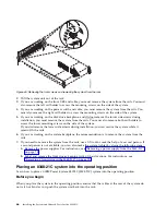
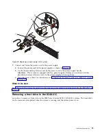
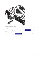
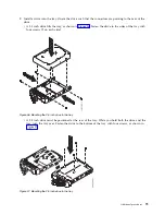
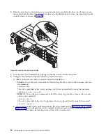
Unlock the drive tray handle by pushing the handle release (A) in the direction shown. The handle
(B)
snaps out towards you. If the handle does not snap out all the way, the drive tray does not slide
out of the system, as shown in Figure 53 on page 77.
76
Installing the System and Ordered Parts for the 8348-21C
Summary of Contents for Power Systems S812LC 8348-21C
Page 2: ......
Page 6: ...iv Installing the System and Ordered Parts for the 8348 21C...
Page 16: ...xiv Installing the System and Ordered Parts for the 8348 21C...
Page 76: ...or or 1 2 3 4 or 1 2 3 4 or 60 Installing the System and Ordered Parts for the 8348 21C...
Page 88: ...72 Installing the System and Ordered Parts for the 8348 21C...
Page 108: ...92 Installing the System and Ordered Parts for the 8348 21C...
Page 109: ......
Page 110: ...IBM Printed in USA...

