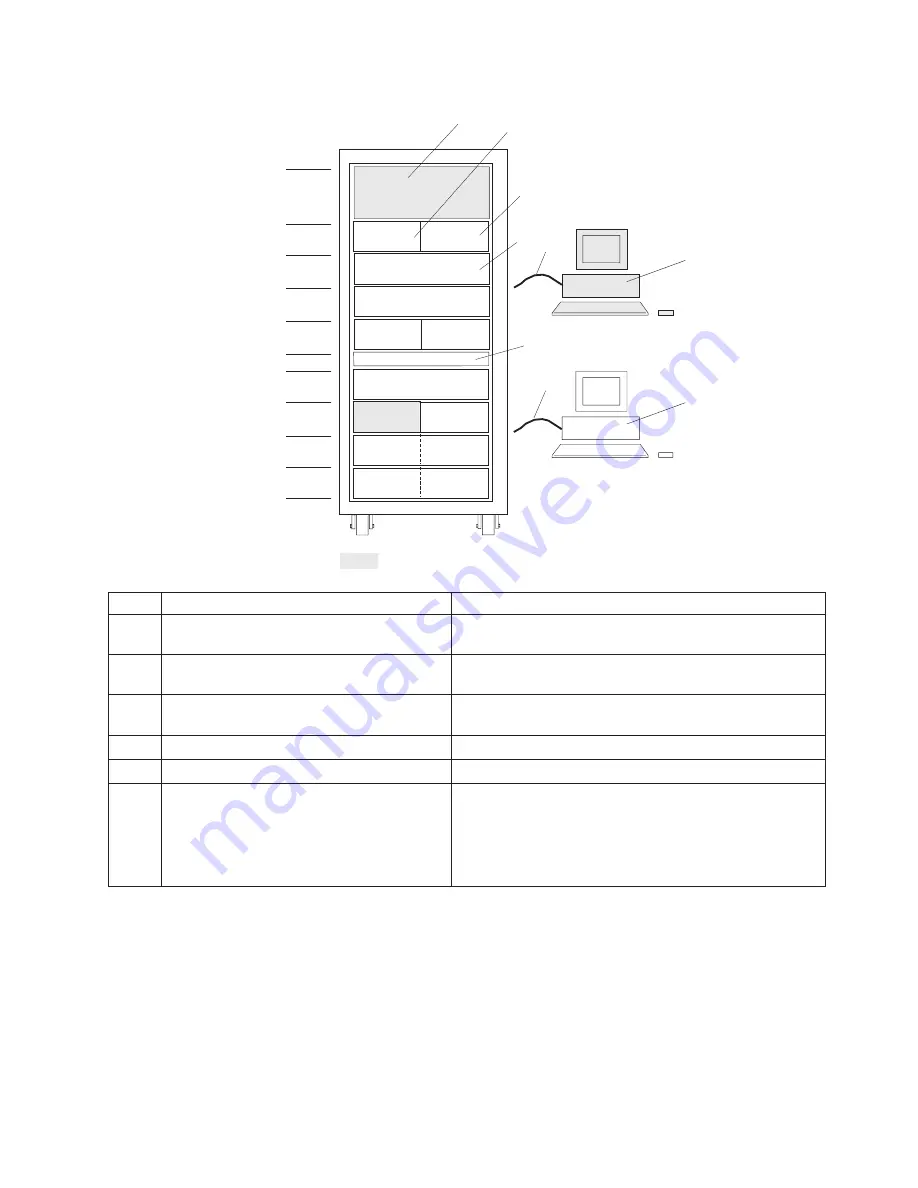
1
7040
Model
W42
Bulk
Power
Subsystem
2
pSeries
655
Processor
Subsystem
Five
or
six
processor
subsystems
maximum
with
five
I/O
drawers.
3
May
contain
sixth
pSeries
655
Processor
Subsystem
or
may
be
empty
4
7040
Model
61D
I/O
Subsystem
At
least
four
I/O
subsystems
must
be
daisy-chained
to
processor
subsystems
to
achieve
the
5-drawer
maximum.
5
Empty
in
this
maximum
I/O
configuration
No
IBF
installed.
6
Hardware
Management
Console
One
standard;
one
optional
7
Cables
v
Five
RS232
cables
(one
to
each
processor
subsystem
for
the
5-processor
configuration).
v
Six
RS232
cables
for
the
6-processor
configuration.
v
Two
RS422
cables
from
each
HMC
attach
to
each
BPC.
A
maximum
of
4
RS422
cables
per
rack.
I/O
drawers
are
ordered
as
a
single
unit,
consisting
of
two
identical
functional
halves.
An
entire
I/O
drawer
can
be
cabled
to
a
single
processor
subsystem
when
the
two
halves
of
the
I/O
drawer
are
daisy-chained
together.
Each
half
of
an
I/O
drawer
can
also
be
cabled
to
a
different
processor
subsystem.
It
is
recommended
that
an
Ethernet
network
be
connected
to
the
system.
Each
HMC
can
connect
to
each
partition
running
on
a
processor
subsystem
to
enable
implementation
of
the
service
functions
that
are
available.
The
Ethernet
network
is
used
for
Service
Focal
Point
(see
the
IBM
Hardware
Management
Console
for
pSeries
Installation
and
Operations
Guide
for
detailed
information).
4
4
4
4
4
4
4
4
8
2
I/O Drawer
I/O Drawer
I/O Drawer
I/O Drawer
Processor
Subsystem
Processor
Subsystem
Processor
Subsystem
Processor
Subsystem
I/O Drawer
1
2
3
EIA units
for each
drawer
4
5
6
7
7
6
Processor
Subsystem
= Minimum configuration items
Appendix
D.
pSeries
655
Description
and
Overview
129
Summary of Contents for pseries 655
Page 1: ...pSeries 655 Installation Guide SA38 0616 03 ERserver...
Page 2: ......
Page 3: ...pSeries 655 Installation Guide SA38 0616 03 ERserver...
Page 14: ...xii Eserver pSeries 655 Installation Guide...
Page 22: ...6 Eserver pSeries 655 Installation Guide...
Page 54: ...38 Eserver pSeries 655 Installation Guide...
Page 101: ...2 1 1 Top of Cassette 2 Handle Chapter 4 Installation and Removal Procedures 85...
Page 125: ...1 Metal EMC Shield 2 Adapter Bracket Chapter 4 Installation and Removal Procedures 109...
Page 128: ...112 Eserver pSeries 655 Installation Guide...
Page 132: ...116 Eserver pSeries 655 Installation Guide...
Page 156: ...140 Eserver pSeries 655 Installation Guide...
Page 204: ...188 Eserver pSeries 655 Installation Guide...
Page 211: ......
Page 212: ...Part Number 80P3836 Printed in USA February 2004 SA38 0616 03 1P P N 80P3836...


